
Phase-Locked Loop Circuit
The Phase-Locked Loop (PLL) is a critical component in various electronic systems, particularly in communication and signal processing. It functions by locking onto the frequency and phase of an input signal, enabling the generation of stable output waveforms. In this configuration, the PLL can produce both triangle and square wave outputs, which are essential for different applications, including modulation and waveform generation.
The use of a quad operational amplifier in this circuit enhances its versatility and performance. Quad op-amps, which contain four independent op-amps in a single package, provide the necessary signal conditioning and amplification required for effective PLL operation. They are particularly beneficial in audio and low-frequency (LF) radio applications, where signal integrity and fidelity are paramount.
In a typical PLL circuit, the input signal is fed into a phase detector, which compares the phase of the input signal with that of a feedback signal derived from the output. The phase detector generates an error signal that is then filtered and used to adjust the voltage-controlled oscillator (VCO). The VCO generates the output signal, which is fed back to the phase detector to maintain synchronization.
The triangle wave output can be utilized in applications requiring linear modulation, while the square wave output is suitable for digital signal processing and clock generation. The selection of output type is determined by the specific requirements of the application, whether it be for audio synthesis, frequency modulation, or other signal processing tasks.
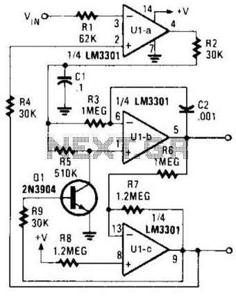
Overall, this PLL configuration with a quad op-amp is a robust solution for generating stable waveforms across a range of frequencies, making it an invaluable tool in modern electronic design. The PLL will lock onto an input signal. Both triangle- and square-wave outputs are available. A quad op amp can be used in this circuit, which should be useful in the audio and LF radio region. 🔗 External reference
Related Circuits
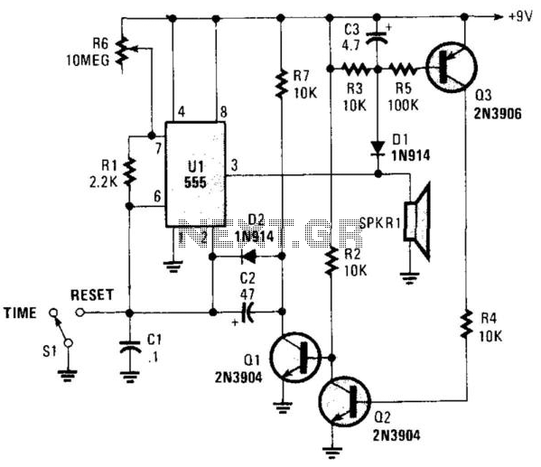
This circuit operates in astable mode and produces a tone at the end of the first period, which can last several minutes. When switch SI is in the time position, transistor Q3 is turned off because pin 3 of...
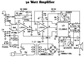
An audio amplifier is an electronic device designed to amplify low-power audio signals, which primarily consist of frequencies ranging from 20 Hz to 20,000 Hz, the human range of hearing. This amplification is necessary to drive loudspeakers and represents...

This sensor switch circuit features nine channels and consists of three integrated circuits along with several resistors. The 74HC147, which has a high input impedance, enables the use of 4.7 MΩ resistors to establish a logic level "high" for...
Assistance is needed for the design of a timing circuit intended to activate a spark plug every 10 or 20 revolutions of a shaft. The timing circuit for firing a spark plug at specified intervals can be designed using a...
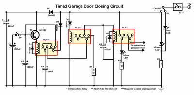
Timer garage door circuit schematic diagram, printed circuit board. The timer garage door circuit is designed to automate the opening and closing of a garage door based on a predetermined time interval. The schematic diagram illustrates the layout and connections...
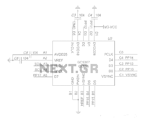
The system employs an optical fingerprint sensor utilizing the ARM Cortex M3 core, specifically the STMicroelectronics 32-bit high-performance microcontroller STM32F205RE. It incorporates a function body composition that utilizes the Sobel edge detection operator, Gabor filtering, image binarization, and various...