
The fluorescent with reactive power compensation circuit diagram
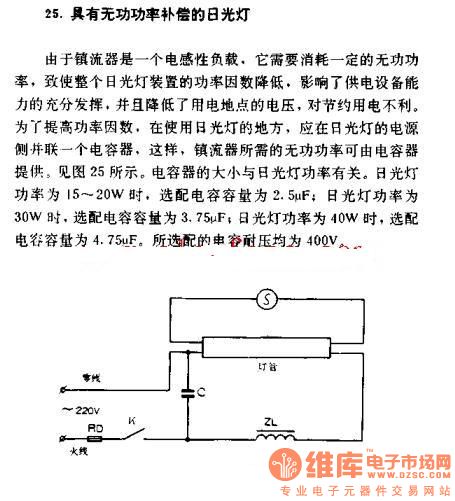
The described circuit configuration addresses the issue of reactive power consumption in fluorescent lamp systems. Fluorescent lamps, typically equipped with electromagnetic ballasts, exhibit inductive characteristics that necessitate reactive power for their operation. This requirement can lead to a reduced power factor, which in turn can cause inefficiencies in electrical systems, potentially leading to increased energy costs and reduced performance of connected devices.
Incorporating a capacitor in parallel with the fluorescent lamp's power supply effectively compensates for the inductive reactance introduced by the ballast. By providing the necessary reactive power, the capacitor improves the overall power factor of the system, thereby enhancing the efficiency of energy usage. The selection of capacitor size is critical and must be matched to the power rating of the fluorescent lamp to achieve optimal performance.
For instance, a 15 to 20W fluorescent lamp would require a capacitor with a capacitance of 2.5 µF, while a 30W lamp would necessitate a 3.75 µF capacitor, and a 40W lamp would require 4.75 µF. It is also essential to ensure that the voltage rating of the capacitor is at least 400V to withstand the operating conditions without failure.
This configuration not only improves the power factor but also contributes to a more stable voltage supply from power stations, thus supporting energy conservation efforts and enhancing the reliability of the electrical system. Proper implementation of this reactive power compensation method is crucial for optimizing the performance of fluorescent lighting systems in both residential and commercial applications.The fluorescent with reactive power compensation As ballast is an inductive load. It needs to consume some reactive power, causing the power factor of fluorescent lamp decreases. It affects the ability of full-powered devices, and reduces the voltage of power stations, and it`s harmful to saving electricity. In order to improve power factor, where the using of fluorescent lamps, fluorescent lamp power supply side should be parallel connected a capacitor, so that the ballast`s reactive power can be provided by capacitor. Figure 25 shows. The size of capacitor and fluorescent power is related. Fluorescent power is 15 ~ 20W, matching capacitance is 2. 5 F; fluorescent power is 30w, the optional capacitance is 3. 75 F; fluorescent power is 40w, the optional capacitance is 4. 75 F. The optional capacitor voltage are 400V. 🔗 External reference
Related Circuits
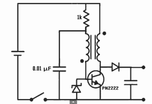
Excellent Joule thief circuit idea! The Joule Thief is a simple yet effective circuit designed to extract usable voltage from low-voltage power sources, such as depleted batteries. This circuit operates on the principle of boosting voltage through the use...
The circuit described is straightforward yet efficient in its operation. The transistor Tr1 is utilized in a grounded base mode, with an input directed to its emitter to facilitate a low impedance input. The circuit is designed to operate effectively...
The simplest way to harness free available energy is by utilizing solar cells. A single efficient solar cell, when paired with a well-configured HHO generator, can produce a significant amount of gas suitable for various applications, all without incurring...
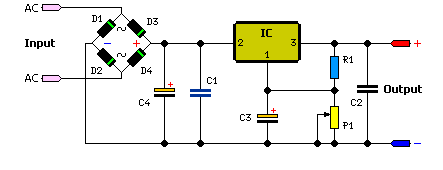
The simple method to power your projects is illustrated in the circuit diagram of a regulated power supply. This compact power supply delivers a stable voltage. This regulated power supply circuit is designed to convert an unregulated input voltage into...
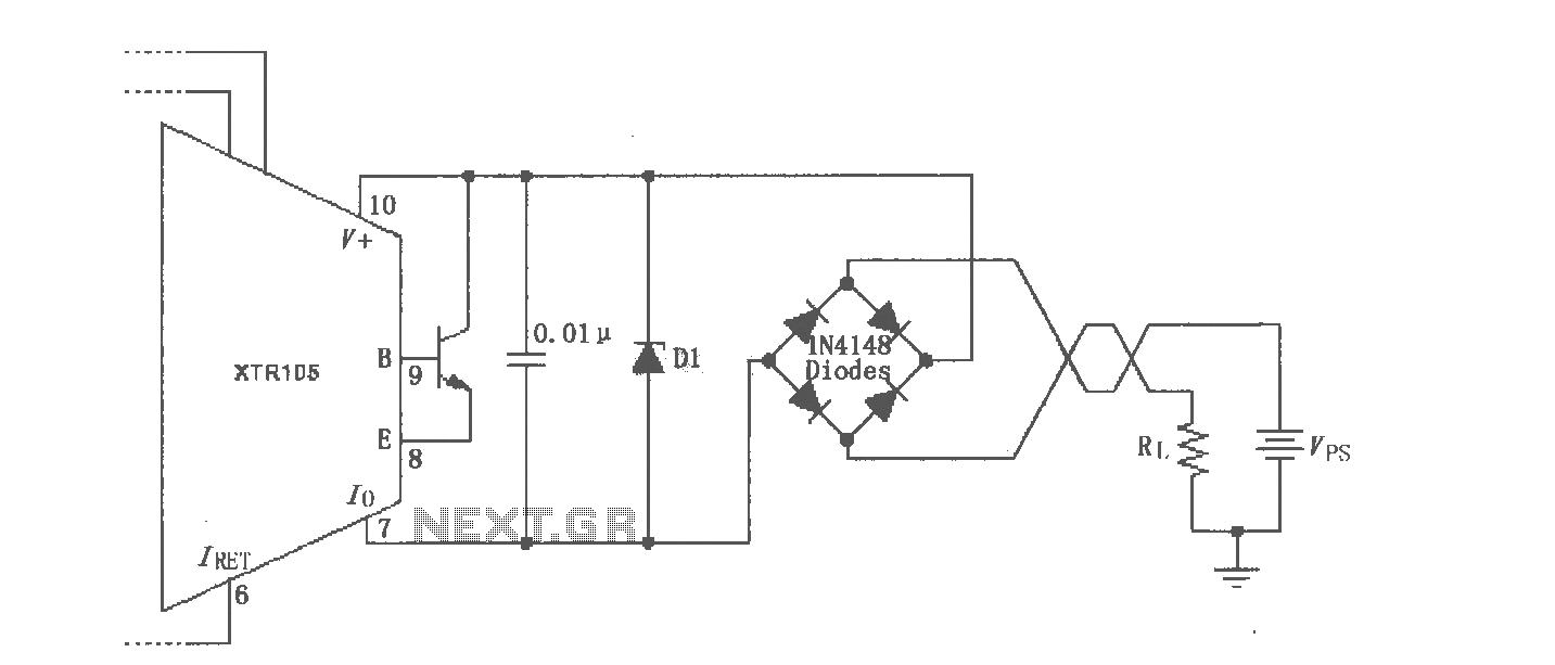
The XTR105 reverse voltage and over-voltage surge protection circuit is illustrated. A Zener diode rated at 36V can be utilized, with options including 1N4753A or 1N6286A. The maximum supply voltage (Vps) should be less than the minimum breakdown voltage...
The circuit in Figure 1 converts pulse information to a clean dc voltage by the end of a single incoming pulse. In another technique, an RC filter can convert a PWM signal to an averaged dc voltage, but this...