
555 toilet floodlight and ventilator automatic control circuit

The electronic switch design utilizes a CK-4 magnetic control switch, which is sensitive to the presence of a magnetic field. The operation begins when the bathroom door is closed; the permanent magnet ZT, mounted on the door, approaches the reed switch GA, which is fixed to the door frame. This proximity causes the reed switch to open, effectively interrupting the circuit.
In this configuration, the components VT1, a transistor, along with resistors R1 and R2, serve to control the current flow based on the state of the reed switch. When the reed switch opens, VT1 is turned off, leading to a high voltage level at pin 2 of the 555 timer IC. This high voltage signals the timer to enter a reset state, which disables the output.
The output of the 555 timer is connected to a relay, labeled J, which controls the power supply to the ventilation fan and light. When the 555 timer is reset, the relay is released, effectively cutting off the power to these devices. This design is particularly useful in applications where energy conservation is desired, ensuring that lights and fans are not left on unnecessarily when the bathroom is not in use.
In summary, this electronic switch system is an efficient solution for controlling lighting and ventilation in a bathroom setting, leveraging magnetic sensing technology to automate power management based on door status. The integration of a 555 timer and relay allows for reliable operation while minimizing energy consumption.The electronic switch is composed of the CK-4 type magnetic control switch and the VT1?R1?R2. When the bathroom door closes, the permanent magnet ZT and the reed pipe GA get close to separate the two touch tablets of GA, VT1 cuts off, pin-2 of IC has the high level voltage, 555 is in the reset state, J releases, the ventilation fan and light has no power. Wh.. 🔗 External reference
Related Circuits
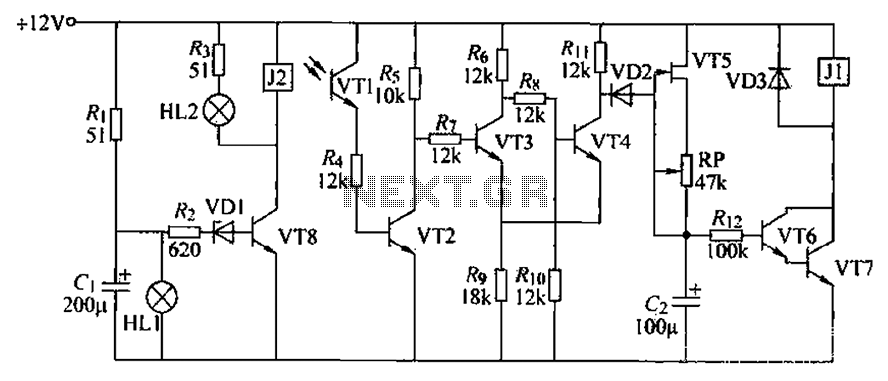
A blocking material monitoring circuit is presented. When the optical path is obstructed by the material, the phototransistor VT1 turns off, which subsequently turns off transistors VT2, VT3, and VT4. This arrangement is coupled to a flip-flop configuration. When...
This circuit provides a visual 9-second delay using 10 LEDs before closing a 12-volt relay. When the reset switch is closed, the 4017 decade counter is reset to the 0 count, illuminating the LED driven from pin 3. The...
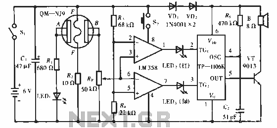
The QM-NJ9 is an alcohol sensor that detects the presence of alcohol by measuring the resistance values between points A and B. When alcohol is detected, the resistance decreases, leading to an increase in potential at point B. As...

The following circuit illustrates a two-transistor DC motor driver circuit diagram. This circuit utilizes the TIP32 transistor. Features: operates in... The two-transistor DC motor driver circuit is designed to control the operation of a DC motor using two NPN transistors,...

A very simple audio amplifier circuit can be designed using the TBA820M audio amplifier integrated circuit with just a few electronic components. This audio amplifier project features a high gain that allows for the detection of sounds underwater. The...
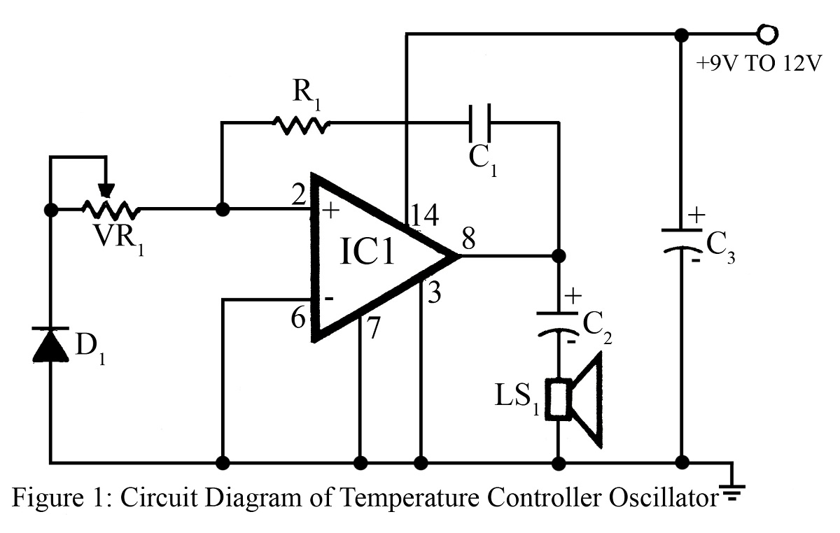
The output frequency or tone of this oscillator circuit varies with the temperature at which the input germanium diode is maintained. The reverse resistance of D1 ranges from 500 ohms to 10 k ohms when the temperature fluctuates between...