
Foxhole crystal radio


Set 3
It has been noted that often these radios were constructed even more simply. The whole thing would have been built on a small, thin piece of wood or shingle, about 1/8 to 1/4 of an inch (3-6 mm) thick, 1 or 2 inches (25-50 mm) wide, and 3 or 4 inches (75-100 mm) long. The coil was wound around one narrow end (the number of turns is uncertain; starting with 100 turns is recommended for experimentation). The blue razor blade would have been screwed or tacked down at one of its ends at the opposite end of the coil. The safety pin and pencil lead (if present, which may not have been the case) would have been rigged up similarly to the previous designs.
The foxhole radio operates on the principle of crystal detection, utilizing a makeshift diode formed by the contact of the pencil lead with the razor blade. This allows for the rectification of the radio signal, converting the alternating current (AC) radio wave into a direct current (DC) signal that can be heard through the headphones. The coil, which serves as the inductive element, is critical for tuning into specific frequencies. The number of turns and the physical dimensions of the coil can significantly affect the resonant frequency, thus experimentation is encouraged to optimize reception.
For optimal performance, the radio should be assembled with careful attention to grounding and antenna connections. The antenna can be a simple length of wire strung up to a height, while the ground connection can be made to a nearby metal object or the earth itself. The capacitor, if included, helps to filter and stabilize the audio signal, enhancing sound quality. Given the improvised nature of the design, various materials may be utilized, and the builder should remain flexible and resourceful in sourcing components.
Overall, the foxhole radio exemplifies ingenuity in electronics, allowing for communication under challenging conditions with minimal resources.Building a foxhole radio is rewarding and the basic setup is very simple. It is, however, difficult to adjust, and it may take several attempts to find a proper razor blade for the detector. This is a project that requires patience and much trial and error, but it will pay off once it begins to work.
It will help to be versed in the construction and operation of crystal sets before building one. It will be especially helpful to read the introductory notes about the coil, detector, antenna, and other components. These sets are extremely simple in construction, but tuning and modification require some basic understanding of theory, as well as practice.
All sets presented here are based on old articles, notes, and people's recollections. There are fairly major variations in design and materials among these plans. It must be remembered that these were improvised under often adverse conditions; there was no "standard" design. With this in mind, take this entire article as a whole, and use it a bit here, a bit there, to build towards a design that works best using modern materials.
Refer to the schematic for wiring and connections. Wind the coil 100 turns around the tube. #22 AWG wire is recommended, but it is likely that whoever was in the field used whatever gauge was in the scrap coil, motor, or transformer they were cannibalizing. Spray / paint the coil with lacquer (or whatever is handy) to set it firmly. Scrape off whatever paint or varnish may be on the wire used for the tuner/slider. Spread the safety pin apart and bend the head 90 degrees to use it as a base for attaching the pin to the base.
The pin should stick up from its bent head, then down to its point where the pencil lead is attached with some of the wire left from winding the coil. The sharpened pencil lead is the detector, which touches the razor blade, which is in turn attached to the base at one of its ends (through the hole) with a screw or tack.
The tuner should be mounted so that it is free to pivot and slide across the coil (see the crystal radio page for basic construction tips). Use a scrap of paper or cardboard as a template for getting the tuner/slider the correct size. Sand off the varnish on the coil where the slider will touch it. Connect the ground and antenna, hook up the headphones, and through much patient adjustment of the detector and slider, you should eventually be able to pick up broadcasts.
A capacitor (.001 - .002 uF) between the earphone terminals improves performance. I have seen more than one example where a cap was improvised from cigarette foil, cut into strips and stacks (the paper backing served as the insulating layers). Simple variable capacitors (condensers) may have also been easily improvised. Not much can be said about so simple a design. The coil was 120 turns around a 2" form (toilet paper tube). The whole thing was tacked down to a board. Pencil lead wasn't used at the time, instead the safety pin point directly contacted the blue (or rusty) razorblade.
There is no tuner, of course, so only one signal will be received, and only if there is a station broadcasting near the correct frequency! Set 3 I have been told that often these radios were constructed even more simply. The whole thing would have been built on a small, thin piece of wood or shingle, about 1/8 to 1/4 of an inch (3-6 mm) thick, 1or 2 inches (25-50 mm) wide, and 3 or 4 inches (75-100 mm) long.
The coil was wound around one narrow end (I am not certain how many times... start with 100 and experiment). The blue razorblade would have been screwed or tacked down (at one of its ends) at the other end. The safety pin and pencil lead (if there was a pencil lead, which there probably wasn't) would have been rigged up in the same manner as in the above sets. 🔗 External reference
Related Circuits
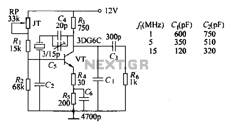
The typical crystal oscillator circuit depicted in the figure is a three-point oscillator designed for capacitance feedback. The oscillator's frequency is influenced by the series and parallel resonant frequencies of the crystal. This type of circuit is commonly known...
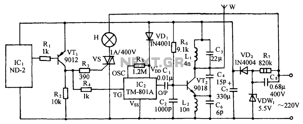
The circuit includes a comprehensive array of components such as vibration sensors, a follower, a lamp relay control circuit, a voice sounding circuit, a high-frequency oscillation circuit, and an AC rectifier buck power supply circuit. The vibration sensor is...

This portable AM/FM radio circuit is designed using the LA1800 integrated circuit (IC) along with several external components. The circuit diagram illustrates that the LA1800, manufactured by Sanyo Semiconductors, requires only a few additional components. The output signal is...
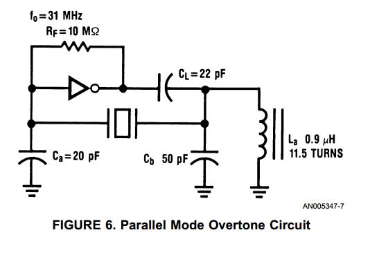
With the advent of high speed HCMOS circuits, it is possible to build systems with clock rates of greater than 30 MHz. The familiar gate oscillator circuits used at low frequencies work well at higher frequencies and either LC...
The concept of a "crystal radio" is typically linked with large antennas and radio broadcasting on long and medium bands. This article discusses experimentally tested detector circuits for VHF receivers designed to listen to FM stations. The discovery of...
This document describes an earlier version of a project that has been found to be quite unreliable. The project is ongoing, with periodic updates being posted until a proper design and rig are developed, at which point a new...