
Vibration sensing Voice FM radio transmitter circuit ND-2 TM-801A

The described circuit functions as an advanced security system designed to protect valuable artifacts displayed in glass cases. The core component, the vibration sensor, is sensitive to disturbances, such as unauthorized attempts to open the cabinet. Upon detecting such an event, the sensor triggers a transmitter circuit that generates an alarm signal. This signal is processed through a high-frequency oscillation circuit, which ensures that the alarm can effectively modulate and transmit the signal over a radio frequency.
The FM radio receiver, which is set to the specific frequency of the transmitter, demodulates the received signal. This allows the voice alarm to be played through speakers positioned strategically within the vicinity of the exhibit. The system's design ensures that staff members are promptly notified of any security breaches, enabling a rapid response to potential theft or vandalism.
Additionally, the lamp relay control circuit can be integrated into the system to activate visual alarms, such as flashing lights, providing a dual alert mechanism that enhances security measures. The AC rectifier buck power supply circuit is crucial for powering the entire setup, ensuring that all components receive a stable voltage supply for reliable operation. This comprehensive approach to security combines multiple technologies to create an effective deterrent against theft and damage to valuable items. Circuit is shown. It includes a full range of vibration sensors, follower, lamp relay control circuit, voice sounding circuit, high-frequency oscillation circuit and the AC rec tifier buck power supply circuit. The vibration sensor attached to relics or precious exhibits plate surface glass case, when someone steal pry cabinet, the transmitter circuit will automatically voice alarm signal, frequency modulation (FM) radio put on duty at the automatic alarm signal demodulation and broadcast through the speakers to remind staff on duty alarm occurs.
Related Circuits

This document presents a circuit diagram of a battery eliminator circuit designed to replace 9V PP3 batteries. It can power any device that operates on a 9V battery. The transformer T1 reduces the mains voltage, while bridge rectifier D1...

The LED flasher circuits operate on a single 1.5-volt battery. The circuit on the upper right utilizes the popular LM3909 LED flasher IC and requires only a timing capacitor and an LED. The LED flasher circuit using the LM3909 integrated...
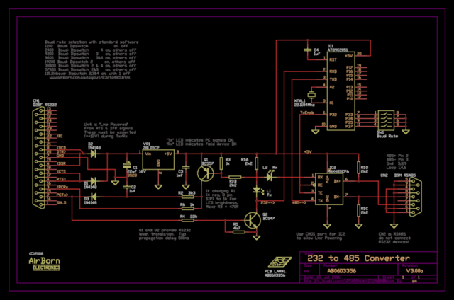
The new version of the RS485 interface addresses the issues associated with RTS control, which was a challenge in the previous design. However, implementing this solution requires a microprocessor, adding complexity to the design. This unit is currently being...
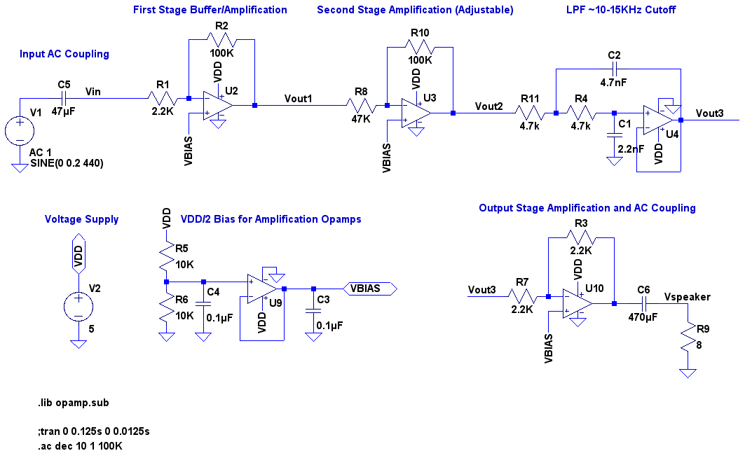
A video showcases a friend, James, playing his electric guitar, connected through an audio echo effect system to an amplifier. The echo effect is implemented on a breadboard rather than through hidden pedals or amp options. Apologies are made...
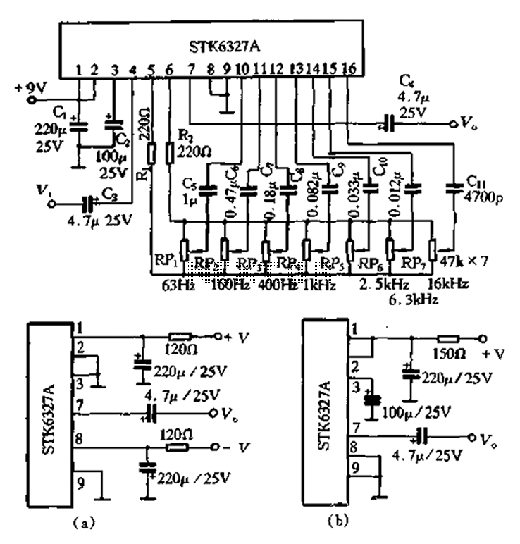
After the universal application of graphic equalizers, a new type of equalizer known as the parametric equalizer has emerged. This equalizer differs in its internal circuit structure and utilizes an external adjustment method that sets it apart from traditional...

Pressing the START pushbutton activates either the headlights or spotlights for a specified duration. After 1 minute, determined by R1 and C1, the lights will turn off as the NE555 timer completes its cycle. The circuit utilizes a NE555 timer...
Warning: include(partials/cookie-banner.php): Failed to open stream: Permission denied in /var/www/html/nextgr/view-circuit.php on line 713
Warning: include(): Failed opening 'partials/cookie-banner.php' for inclusion (include_path='.:/usr/share/php') in /var/www/html/nextgr/view-circuit.php on line 713