
Parallel crystal oscillator

The Pierce oscillator is a widely used configuration in electronic circuits for generating stable frequencies. It typically consists of a crystal, an amplifier (often a transistor), and passive components such as resistors and capacitors. The crystal used in the circuit provides a highly stable frequency reference due to its mechanical resonance properties.
In this configuration, the circuit operates by feeding back a portion of the output signal through the crystal, which acts as a frequency-selective element. The crystal's characteristics define the oscillation frequency, which is typically very precise and stable. The feedback loop is crucial for sustaining oscillations, and the choice of components like C1, G, and C3 significantly influences the overall performance, including start-up time, amplitude stability, and frequency accuracy.
The transistor (3DG6C) serves as the active element that amplifies the signal, enabling the circuit to maintain oscillations. The values of the capacitors and any resistive components must be carefully selected to ensure that the circuit operates within the desired frequency range while also providing the necessary phase shift for oscillation.
The Pierce oscillator is particularly advantageous in applications requiring low phase noise and high frequency stability, making it suitable for use in clocks, RF transmitters, and various communication systems. Understanding the interplay between the crystal properties and the surrounding circuit elements is essential for optimizing the performance of this oscillator configuration.Actual typical crystal oscillator circuit as shown in FIG. The three-point oscillator circuit to meet the original composition is for capacitance feedback oscillator. When the oscillator oscillation frequency of the series and parallel resonant frequency of the resonant frequency of the crystal is between crystal was emotional, it may oscillate oscillator. This circuit is commonly referred to Pierce (Pierce) oscillator, called parallel fork type crystal oscillator.
Transistors 3DG6C, other parameters as shown 21-31 in FIG. Pierce oscillator frequency by the c1, G, C3 decision circuit and crystal composition. Parallel crystal oscillation frequency of between A series resonant frequency and the parallel resonant circuit of quartz crystal frequency.
Related Circuits
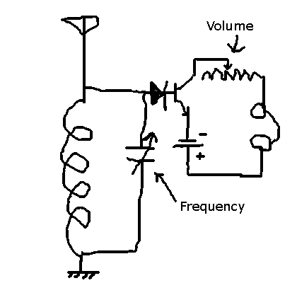
This circuit allows the selection of a station by adjusting the capacitance in an LC circuit. However, the signal remains modulated. To demodulate the signal, a second capacitor is required, but the function of this component is unclear. The...
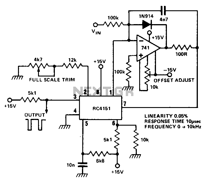
The RC 4151 precision voltage-to-frequency converter generates a pulse train output that is linearly proportional to the input voltage. The RC 4151 is a highly accurate voltage-to-frequency converter designed for applications requiring precise frequency output based on varying voltage levels....
One example of the phase shift oscillator is the Bubba oscillator. This oscillator achieves a 45-degree phase shift for each section from a quad op-amp package. The Bubba oscillator is a type of phase shift oscillator that utilizes a...
The frequency formula of a 555 oscillator is well-known. For given resistors and capacitors, the frequency can be calculated using a specific formula derived from mathematical principles. The 555 timer IC is widely used in various applications, including oscillators, timers,...
A precision oscillator can be constructed using a quartz crystal; however, with appropriate component selection, it is also possible to build one using an RC (resistor and capacitor) circuit. An RC oscillator generates an oscillating signal through the use of...
A voltage-controlled oscillator (VCO) is an electronic signal generator that produces a signal with a variable frequency, which is dependent on an input voltage level. A voltage-controlled oscillator is a fundamental component in various electronic applications, including phase-locked loops (PLLs),...