
Fred Nachbaurs Theremax modifications
The Theremax theremin design demonstrates significant advancements in sound control and modulation capabilities compared to traditional theremins. The integration of frequency-to-voltage converters allows for enhanced interaction with external devices, making it a versatile tool for musicians and sound designers. The innovative volume control mechanism, which relies on a separate oscillator pair, provides a broader dynamic range, facilitating expressive performances. The incorporation of velocity-sensitive features adds a layer of responsiveness, allowing for nuanced sound variations based on playing intensity.
The modifications suggested enhance the overall user experience, addressing issues such as volume drop and sensitivity in the Timbre fader. Careful attention to component selection and configuration can optimize performance, ensuring the Theremax meets the expectations of both amateur and professional users. The attention to detail in the circuit design and modification process highlights the importance of precision in electronic instrument development, where even minor adjustments can significantly impact functionality and sound quality.The purpose of this page is neither to give a comprehensive review of this popular theremin design, nor to be an introduction to the fascinating and quirky world of theremins in general. If you`re wondering "What the heck is a theremin ", check out the links on the index page. That being said, there are a few comments that bear making before we g et on with improving an already excellent design. The "Theremax" is a nice implementation of the classic Theremin idea. It does everything that the more traditional designs do, plus it contains added circuitry (i. e. "frequency- to- voltage converters, " or more simply F-V`s) to convert the pitch and volume signals into "CV" (constant voltage) signals that can be used to control external devices. For this reason its designer has opted to call it a "Gestural Controller. " Theremax handles volume unlike any other design I`ve seen. Rather than using a simple LC circuit that is detuned by hand proximity, it employs a separate oscillator pair with its own frequency-to-voltage converter to effect the volume change.
The result is a dynamic range vastly greater than that afforded by previous designs such as the SWTP design informally adopted by TECI (Theremin Enthusiasts Club International). Theremax uses velocity (derivative of volume) to modify the sound by introducing asymmetry (and therefore even-order harmonic distortion) into the VCA.
The idea here is to give a feeling of articulation on notes that are played with high velocity, much as a piano sounds different when struck hard than when played softly. The "Timbre fader" was another feature that convinced me to buy, work with, and help promote this fascinating device.
This allows a transition between the classic sine-wave sound, and a harder, more penetrating square-wave sound. In practise, however, I found the last two features slightly lacking. However, after implementing the modifications detailed below, (and adding my "DIS*PLAYER" circuit), I was completely content with the instrument`s performance.
As supplied, there is a noticable drop in volume when fading all the way to the right of the Timbre pot (square-wave sound). Since this is easy to fix, I`m mentioning this one first. Simply replace R40 with a lower value (I used 150K). This gives a smoother, more even transition between sine and square wave sounds. As often happens in the wonderful world of mods, the left end of the pot now gets a little touchy, with the square-wave sound coming up quite rapidly.
Replacing R81 (the 100K Timbre pot) with a log-taper (audio taper or "A" type) pot of the same value as the original solves that little inconvenience quite nicely. The other shortcoming was that, to my ear at least, the timbral change on rapid attack was hardly noticeable.
I verified that the circuitry was working by using my scope to check that, indeed, the operating point of Q11 was being shifted by the increase of velocity voltage on the wiper of the velocity pot. Another problem was that the velocity voltage took a long time to decay after an attack. Investigation showed that part of the reason was leakage current through the 10 µF electrolytic C25 (quite a large value), and part of it was just the high impedance in the circuit.
IMPORTANT NOTE: While the modification is perfectly safe for your instrument if followed verbatim, you should not attempt this if you`re uncomfortable with cutting circuit traces or soldering parts "dead-bug"-style on your instrument`s circuit board. Also, this modification should only be undertaken once you`re certain that your instrument is functioning correctly as per the manufacturer`s instructions.
Remove transistor Q7, and set it aside. In its place, install a general- purpose PNP transistor, such as a 2N4403 or 2N3906 (henceforth called Q7B). However, install it backwards; the flat side of the transistor should face the opposite way as shown on the silkscreen.
This puts its collect 🔗 External reference
Related Circuits
After attempting to use this reportedly "pretty good" microphone in a variety of situations with some "pretty bad" results, I dissected the power supply and found the same audio transformer that’s in their 180-in-one project kits! This DAT-Heads Digest...
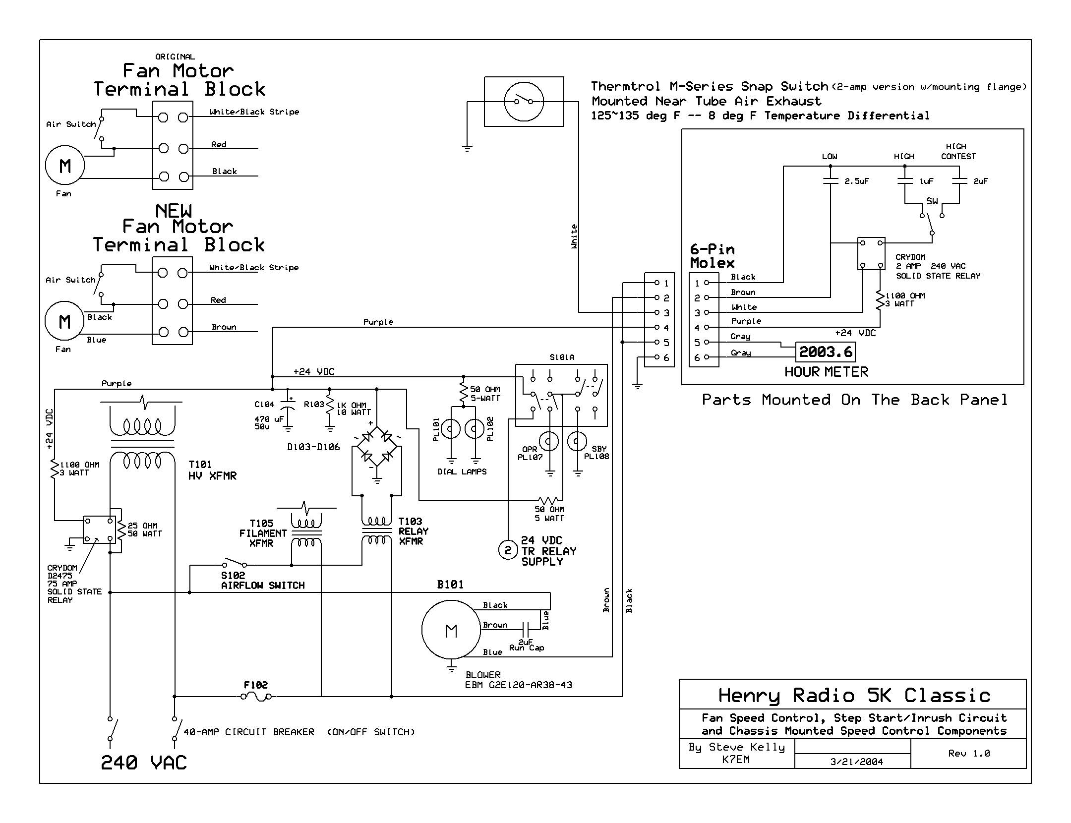
The back cover has been removed, revealing the upper deck of the power supplies and the original Dayton 2C915A blower (220VAC - 140CFM) mounted to the cabinet's underside. The RF deck enclosure has also been taken off. The upper...
Upgrading to a 3-prong AC cord is a common modification, as is the replacement of filter capacitors. Switching coupling capacitors to brands like Orange Drops or other boutique options is also popular, often enhancing the appeal in online auctions....
Voltage-controlled shape on each oscillator, calibrated 1V/octave keyboard input, external gate input socket, portamento/glide, patchable voltage inverter, extra input channels, improved panel components, power supply replacement, mains connectors. The described circuit features a voltage-controlled oscillator (VCO) architecture with several key...
This is a 16x2 switcher, providing ample room for expansion. While the cameras are satisfactory, the primary requirement was the capability to pan and tilt the selected cameras to adjust the view as needed. Extensive research revealed that most...
The original firmware is functional on amateur radio bands; however, it lacks user-friendliness. Wulf-Gerd, DL1FAC, has developed a new firmware that is significantly more suitable for amateur radio users. This firmware is open source, allowing for flexible frequency adjustments,...