
X-10 Ninja Pan and Tilt Modifications
The circuit design involves a 16x2 switcher configuration, allowing for the connection of multiple cameras and facilitating their control through a centralized system. The primary focus is on the development of a hard-wired control mechanism utilizing RS-485 communication, which is well-suited for long-distance data transmission. The Ninja Pan and Tilt mounts will be modified to incorporate the ATTiny2313 microcontroller, which will manage the pan and tilt functions through a serial interface. This approach allows for real-time control of multiple cameras without the limitations associated with RF communication.
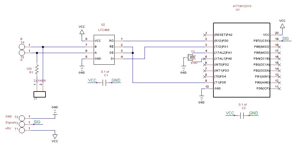
The schematic will illustrate the connections between the ATTiny2313, the servos responsible for the pan and tilt movements, and the power supply circuitry. The existing RF receiver board will be replaced with a custom circuit that interfaces directly with the ATTiny2313, ensuring that the microcontroller receives the necessary signals to control the servos accurately. The power supply section will include a 5V regulator to provide stable voltage to the microcontroller and servos.
In summary, this project aims to enhance the functionality of the Ninja Pan and Tilt Camera Mounts by implementing a hard-wired RS-485 communication system, allowing for improved control and expanded capabilities while maintaining compatibility with existing hardware. The use of the ATTiny2313 microcontroller will facilitate the execution of complex control algorithms and ensure reliable performance across multiple camera units.This is a 16X2 switcher so it gives me plenty of room for expansion. While the cameras are nice, what I really wanted was the ability to pan and tilt selected cameras to change the view if necessary. I did quite a bit of searching and most of the pan and tilt mounts were more than I was willing to pay.
I also considered building my own but, while doable, was more packaging than I wanted to mess with. I finally settled on the Ninja Pan and Tilt Camera Mounts from X-10. These are relatively inexpensive - I got my last one on eBay for $30 - and appear to be reasonably well built. The negative to these mounts, at least for me, is that they are controlled by an RF remote and the knock on them is that they have a pretty limited range.
My cameras tend to be spread out and I wanted to control them from my home control system located in the basement so that didn`t seem to be a very attractive option. There are quite a few sites around the internet devoted to hacking these devices but most of them seem to be aimed at increasing the range of the remotes.
There`s even a few where someone has replaced the processor in the Ninja with their own processor and custom code. Since my cameras are all hard-wired, I decided to go with a hard-wired approach for the Ninja as well and convert them to operate an an RS-485 network.
That`s what this page is all about. As I mentioned previously, there is quite a bit of information available on the web and the most important piece of information I needed was the protocol currently used by the Ninja. I found the best descriptions on Ed Cheungs comprehensive home automation site (although the data was actually provided by Dennis Hawkins) and Dave Houston`s excellent web site.
I also found all of the details of how the Ninja hardware worked on this site. This last modification consisted of replacing the micrcontroller with an SX controller and changed the Ninja to be controlled over a serial link to a PC. It also involved a new protocol and several new capabilities. While I liked this approach, I wanted to control several Ninjas and the distance would just be too great for an RS-232 connection.
So let`s get started. In the shot on the left you can see the PCB, main processor, the 5 volt regulator under the mess of wiring, and the ribbon cables which supply the power signals to the servos located under the PCB. In the shot on the right you can see the RF receiver board which is responsible for receiving the RF signal and transmitting it to the main processor.
This board has 3 wires connecting it to the main board - the white and black wires which are +5V and Ground as well as the yellow wire which is the signal to the main processor. Since we are not using RF, we will remove this board and then design our new interface to fit in the same location using the same wires.
If we do this correctly, the processor will never know the difference. Before removing the board completely, I cut the wire to get a better look at the signal going to the Ninja processor. In order to see this, I used my Logic Analyzer from Saleae LLC. This is a great product at a great price and, if you`ve never used one before, it`s a great tool for understanding whats going on with your circuits and programming.
So when I hooked up the analyzer to the yellow signal wires, here`s what I got: My choice was to replace the RF board with my own board using an Atmel ATTiny2313 AVR controller. I`ve been using Atmel processors for a while now and am very pleased with their performance and, while I can program them in assembler, I usually choose Bascom-AVR.
This is a very nice Basic compiler and produces excellent and fast code. In order to make sure that I could replicate the Ninja protocol, I installed a Tiny2313 on my breadboard 🔗 External reference
Related Circuits
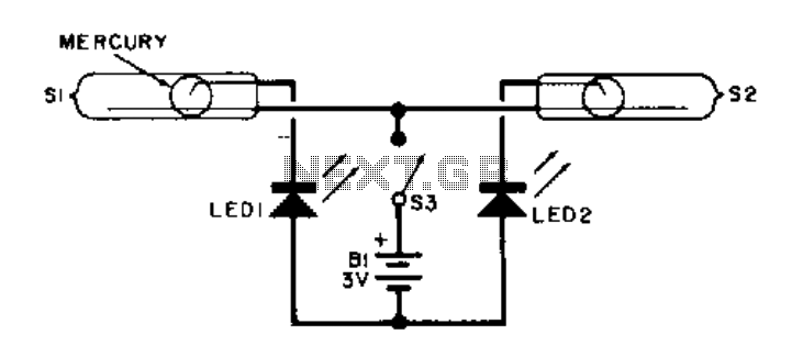
This electronic level utilizes two LED indicators in place of an air bubble. When the surface tilts to the right, one LED illuminates; conversely, if it tilts to the left, the other LED illuminates. Both LEDs light up when...
Here is the schematic, PC board pattern, and parts placement for a "Fantastic Atom Expander". This circuit produces an "exploding atom" effect using 98 LEDs. The LEDs can be any colour but blue. For a very interesting effect, make...
I have been researching the appropriate voltages for charging, particularly regarding this topic. The proper voltage levels for charging various types of batteries are critical for ensuring efficiency and longevity. For instance, lithium-ion batteries typically require a charging voltage of...
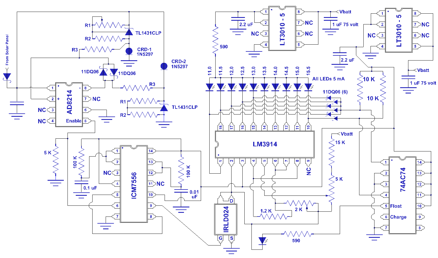
Switching to alternative power sources can help reduce electricity bills. The photovoltaic module or solar panel described here is capable of generating renewable energy. The photovoltaic module, commonly known as a solar panel, is a device that converts sunlight into...
The project described in this article is a constant Q, fully expandable graphic equaliser. Where most "conventional" graphic EQ circuits have a Q that is dependent on the setting of the pot, this one maintains the same Q at...
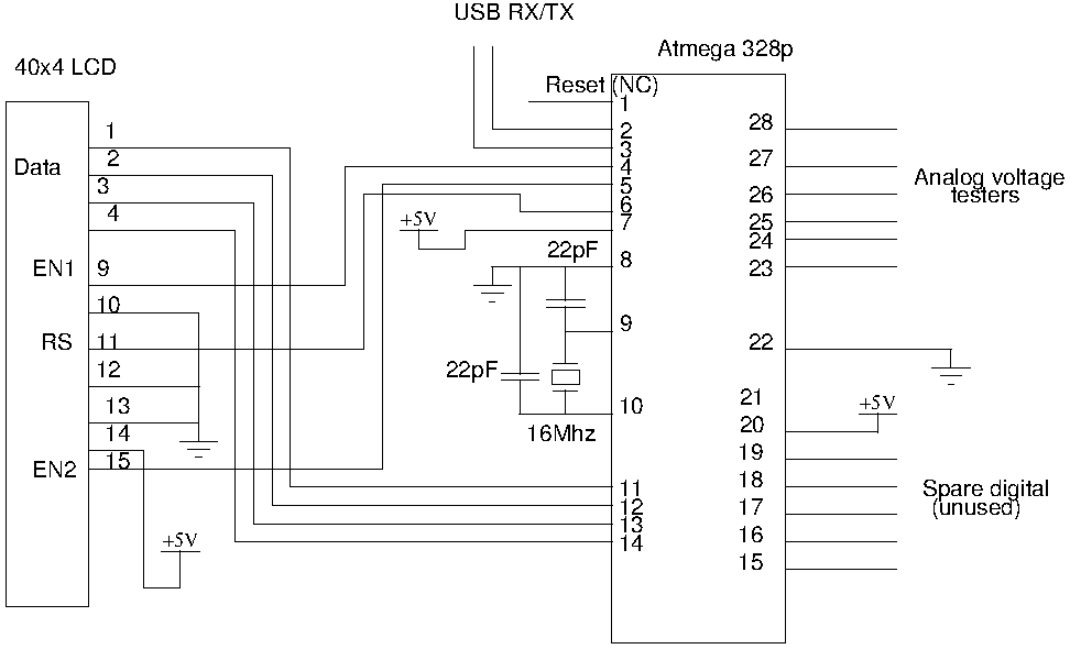
Drive a four-line LCD panel using an Arduino. The project initially aimed to control the LCD for displaying arbitrary information but evolved to include functionalities such as timekeeping, EEPROM read/write operations from the Atmel 328p, and voltage measurement. Multiple...