
Henry Radio 5K Classic Blower Modifications
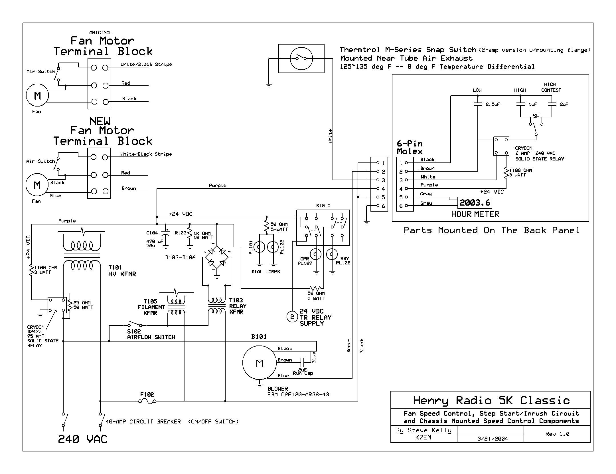
The modifications to the RF deck and blower installation are critical for optimizing the thermal management of the system. The use of the EBM G2E120-AR38-43 blower, with its advanced features such as the external rotor design and split capacitor motor, significantly enhances airflow efficiency while reducing operational noise. The implementation of anti-vibration mounts ensures stability and minimizes mechanical noise, which is essential in high-performance applications. The careful design of the mounting plate and the gasket system further contribute to the longevity and reliability of the assembly by preventing potential wear and tear due to vibration. The planned modifications to the RF deck will allow for improved airflow dynamics, ensuring that the cooling requirements of the tube anodes are met effectively. By utilizing AutoCAD for precise template creation, the design process is streamlined, allowing for accurate adjustments to the exhaust holes to accommodate the new chimneys. Overall, these enhancements reflect a thorough approach to improving the performance and reliability of the electronic system.Back cover removed showing the power supplies upper deck and the original Dayton 2C915A (220vac - 140cfm blower) mounted to the underside of the cabinet. The RF deck enclosure was removed. Upper deck of the power supply with the original blower removed. From left to right you can see the Filament transformer, HV filter cap in the rear, Bleeder resistors (back right) and the Relay/Control circuit
transformer (front right). After a great deal of research and measuring, I chose a EBM G2E120-AR38-43 (click link for catalog - 1MB PDF file - see page 19) blower as a replacement for the Dayton. The new blower uses a split capacitor motor which is much easier to speed control by using a capacitor in series with one of the motor leads.
Another advantage is the `External Rotor` design which places the motor in the center of the squirrel cage. The motor runs very cool. The EBM blower has a cast aluminum housing and zero maintenance ball-bearings in the motor. This picture shows the air switch mounted. Henry uses an air switch to turn on the tube filaments and relay power supply only when sufficient airflow is present to cool the tubes.
End view showing the air vane attached to the air switch. The new blower has a much wider squirrel cage which allows it to move more air at a slower, quieter speed than the original Dayton blower. After dealing with all of the vibration problems of the original blower, I decided not to take any chances with the new one.
After more research I found a company that makes small Anti-vibration Mounts ( Part # 62490-2 ) that were perfect for my application. Brad, K7ZSD, made the mounting plate for the new blower out of 3/16" aluminum plate. After further experimenting, it became obvious that an extension arm on the plate would be necessary to properly distribute the weight of the fan.
Here`s a side view of the new blower mount. Each anti-vibe mount is attached to the plate with four 4-40 screws. The entire plate is attached to the amplifier chassis with 8-32 screws and Ny-Lock nuts. The screws run through the center brass bushing in each anti-vibe mount. LockTite was used on the 4-40 hardware. The new blower installed. I used a hollow foam weather stripping gasket to fill the gap between the top of the blower mounting plate and the underside of the chassis. The gasket material is shaped like the letter `D` with an adhesive on the flat side of the `D`. The hollow portion minimizes any vibration transfer between the plate and the chassis. At the top center of this picture you can see the HV, Filament and Control plugs protruding from the bottom of the RF deck.
Here you can see the blower with it`s starting capacitor and terminal strip mounted. The original blower also had the same terminal strip mounted on it. The HV, Filament and Control cables have been plugged into the RF deck. That completes the blower installation. The next step will be the necessary modifications to the RF deck to allow more efficient airflow from the blower through the tube anodes. The original exhaust hole above each of the 3CX1200A7s. The top of the tubes anode is visible at the center of the image. You can also see the white Teflon chimney which sits on the top of each tube. I made paper templates (drawn in AutoCAD) to facilitate the required enlargement of each hole. The original hole was filed out to the first line on the template. The second line represents the tube anodes outside diameter. The outside line represents the outside diameter of the new chimneys. Looking down on the tube sockets wit 🔗 External reference
Related Circuits
This circuit illustrates the high and mid-frequency sections of a car radio. The medium wave band I operates within the frequency range of 520 to 950 kHz, while Poland II operates between 900 and 1640 kHz. The circuit employs...
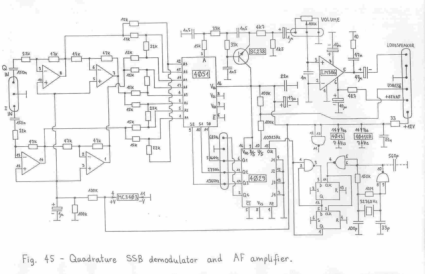
This article is a local and enduring copy derived from replica sites. It appears to have undergone significant revisions in 2006, leading to the disappearance of the original version. When considering SSB transceivers, the primary question is whether it...
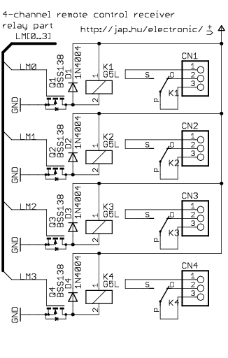
This is a general-purpose remote control project utilizing programmable PIC microcontrollers. Schematics are provided for using infrared (IR) or radio frequency (RF) media. If microcontroller programming is unfamiliar, fixed encoder and decoder integrated circuits can be employed instead. Well-known...

With the P1 we regulate the intensity of sound. With the P2 we regulate the frequency of reception. Optionally: If you want to check the frequency with your PC it will be supposed you make the following energies: You...
Here is a simple radio that is easy to build and inexpensive. In fact, you probably have all the parts you need in your junk box. You'll be surprised at the great reception with this little set. More: The...
A noise generator with a wideband output signal is useful for adjusting receivers and various types of HF equipment. A noise generator is an essential tool in the field of electronics, particularly for testing and troubleshooting radio frequency (RF)...