
Frequency Counter

The circuit incorporates the Intersil 7216 frequency counter IC, which is designed to measure frequencies up to 10 MHz. To accommodate higher frequencies, a 100-MHz prescaler is implemented, allowing the circuit to effectively handle input signals that exceed the base frequency limit. The prescaler reduces the frequency of the incoming signal to a manageable level for the counter IC.
An additional frequency divider, designated as IC3, is included in the design. This component further divides the frequency of the signal by a specified factor, as indicated on S7 in the schematic. This capability is crucial for extending the operational range of the counter, enabling it to measure frequencies beyond 10 MHz and up to the limits imposed by the prescaler.
The output of the frequency counter is presented on a multiplexed display system. The use of MAN6710 2-digit red common anode 7-segment LED displays enhances visibility and readability of the measured frequency. The multiplexing technique allows for efficient use of the display segments, reducing the number of required connections while maintaining clear output visibility.
The overall design emphasizes precision and versatility in frequency measurement, making it suitable for various applications in electronics testing and signal analysis. The combination of the Intersil 7216, prescaler, and additional frequency divider presents a robust solution for high-frequency counting tasks. Built around an Intersil 7216 frequency-counter IC, this counter has a basic range of 10 MHz, a 100-MHz prescaler, and an extra frequency divider (IC3). This divider divides by an extra factor, as marked on S7 (see schematic), to extend the range of the counter. The display is multiplexed. MAN6710 2-digit red common anode 7-segment LED displays were used on the prototype.
Related Circuits
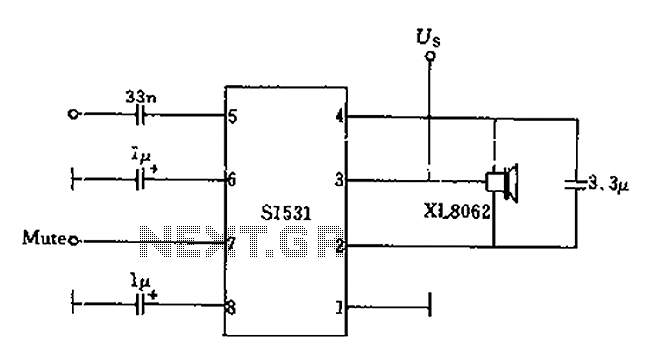
The battery voltage is 1V for a low-frequency amplifying circuit, which can operate with a power supply voltage ranging from 1V to 1.7V, making it suitable for use with small batteries. The circuit provides an output power of 80mW...
As equipment becomes increasingly compact, designers are often required to reduce the size of displays. However, this can compromise the usefulness of the display. Many individuals find it challenging to read small displays, which can be particularly frustrating. In...
The objective of this lab is to create a decimal counter that counts from 0 to 99 using the 80X51 microcontroller. A C program must be written for this purpose, which will then be compiled using the C51 compiler...
Inquiry regarding the circuit design involving ICs 4029N and 4511N, specifically questioning whether these components function as a driver/decoder. The datasheet was consulted but did not provide precise specifications. The IC 4029N is a binary up/down counter that can count...
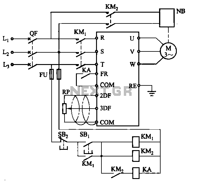
Electromagnetic brake motors consist of a motor and an electromagnetic brake, forming a standard assembly. The circuit diagram is provided. In this configuration, FR represents the forward run and stop command terminal, while the intermediate relay KA is employed...
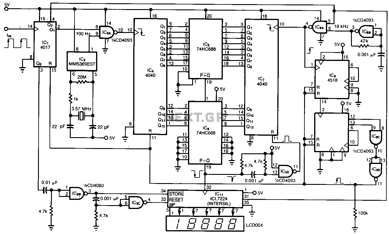
This tachometer allows for the measurement of heartbeats, respiratory rates, and other low-frequency events that occur at intervals ranging from 0.33 to 40.96 seconds. The circuit detects the frequency, calculates the corresponding pulses per minute, and updates the LCD...