
Decimal Counter Using Two 7-segment displays and an 8051
The circuit design consists of the 8051 microcontroller interfaced with the LSD5061-11 7-segment displays. Each segment of the display is connected to specific output pins on the 8051, allowing for direct control over which segments are illuminated. The microcontroller operates at a standard voltage of 5V, and the 7-segment displays are designed to function within this voltage range, ensuring compatibility.
The lookup table is essential for efficiently managing the display outputs. Each entry in the table corresponds to a specific digit, and the values are derived from the required pin states to illuminate the segments correctly. For example, the entry for displaying the digit "0" is represented by the bit pattern 1100 0000, indicating that segments s1 to s6 are active (0V) while s7 is inactive (5V). The remaining entries in the lookup table must be populated with similar bit patterns for digits 1 through 9, ensuring that the display can accurately represent all decimal numbers in the range.
The SetDisplay function is designed to handle the input value and verify its validity. If the value is within the acceptable range, it retrieves the corresponding display configuration from the lookup table. If the value is out of bounds, it returns an error value, which is indicated by lighting segment s7.
The delay function is implemented as a simple nested loop that creates a pause in the execution of the program, allowing the displayed numbers to be visible to the user for a short period before the next update occurs. The main loop continuously updates the counter, displaying both the ones and tens places, ensuring that the display reflects the current count accurately.
This circuit design effectively demonstrates the integration of microcontroller programming with hardware components, providing a practical application of digital electronics principles. The use of a lookup table simplifies the process of controlling the 7-segment display, while the structured approach to programming ensures clarity and functionality.The purpose of this lab is to implement a decimal counter which counts from 0 to 99. You will have to write a C program for the 80X51 micro-controller. You will then compile your C program using C51 compiler and burn it unto an 8051 stand alone chip. You will also have to do some wiring in this lab. The 8051 chip requires some connections to funct ion properly, and the 7-segment displays need to be wired to the 8051. Schematics are provided below. Before you can write your C program, you have to understand how the 7-segment displays work. The 7-segment displays used in the lab are the LSD5061-11 display. Each of the segment corresponds to a pin (see below for the pinout). In order to light up a particular segment, it`s pin must be set to 0V. Since these pins are connected to the 8051, we simply set the corresponding pin on the 8051 to `0`. To turn a segment off, the pin must be set to 5V. This is done by setting the corresponding pin on the 8051 to "1". Instead of going through each of the seven pins and setting them to `1` or `0` each time we want to display a number, we will use a lookup table unsigned char LookupTable[11] = { }. The location of the entry in the table corresponds to the correct pin settings to display that number.
Simply, LookupTable[0] returns the correct pin settings to display a "0" on the 7-segment display. Now we have to figure out the correct entries into the table. We know that in order to display a "0" on the 7-segment display we need to turn on segments s1, s2, s3, s4, s5, and s6. To turn a segment on, we set the corresponding pin to "0". Segment s7 will need to be turned off. To turn off this segment we set the corresponding pin to "1". Therefore, the pins will need to be assigned the following values: The bit pattern desired is 1100 0000 (remeber that pin 8 is the highest bit).
We then convert the values into hexadecimal 1100 -> C and 0000 -> 0. We fill in the table with this value 0xC0. The "0x" is needed before the actual value to indicate to the compiler that it is a hexadecimal value. Now when we call LookupTable[0] it will return the proper configuration to display a "0" on the 7-segment display.
You will need to fill in the rest of the values (1-9). LookupTable[10] will indicate an error has occured, at this location segment s7 will be on, the remaining segments will be off. (If you want, you can also look at the 7-segment display datasheet. ) /* P0, P1, P2 and P3 are predefined port names and are bit addressable */ unsigned char SetDisplay(unsigned char value){ unsigned char LookupTable[11] = { 0xC0, .
}; /* check to see if "value" is in bounds, if not return an error */ if( ) { /* return appropriate value */; } else { /* return error value */; } } /* Delay function */ void delay() { int i, j; for(i=0; i<1000; i+) for(j=0; j<100; j+) i = i + 0; } void main(void){ unsigned char count = 0; /* value held in one`s place */ while(1) { /* determine and display the one`s place */ /* determine and dipslay the ten`s place */ /* update the counter (remember to keep it within bounds)*/ delay(); } } 🔗 External reference
Related Circuits
This quarter, the graduate seminar at UCR will focus on network theory. A few students are beginning work in this area, making it an opportune moment to delve deeper into the foundational aspects of the subject. Bicategories of spans...
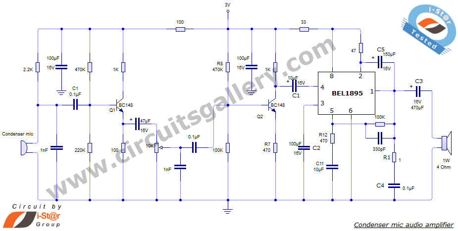
This document presents an audio amplifier circuit suitable for use in walkie-talkies, low-power transmitters, and packet radio receivers. The circuit utilizes a condenser microphone audio amplifier that delivers high-quality audio output of 0.5 watts at 3 volts. The design...
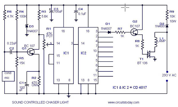
A simple musical light chaser circuit diagram and schematic using IC CD4016. This circuit blinks lights in response to sound, audio, or music output, causing 10 lights to dance according to sound frequency. The musical light chaser circuit utilizing the...
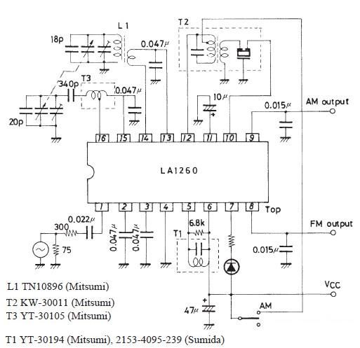
The FM IF MW radio receiver circuit schematic utilizes the LA1260 integrated circuit (IC) for AM and FM radio receiver electronic projects. The LA1260 incorporates numerous functions and features essential for radio receiver applications, including a high signal-to-noise ratio...
This simple LED flasher circuit will alternately turn ON and OFF two LEDs. The first LED will illuminate when the second LED is OFF for a certain duration, and then the process will repeat. The LED flasher circuit operates using...
This circuit illustrates a remote control system utilizing a radio telephone circuit diagram. Features include the ability to switch appliances from any distance, overcoming various limitations. The remote control circuit employs radio frequency (RF) technology to facilitate wireless communication between...
Warning: include(partials/cookie-banner.php): Failed to open stream: Permission denied in /var/www/html/nextgr/view-circuit.php on line 713
Warning: include(): Failed opening 'partials/cookie-banner.php' for inclusion (include_path='.:/usr/share/php') in /var/www/html/nextgr/view-circuit.php on line 713