
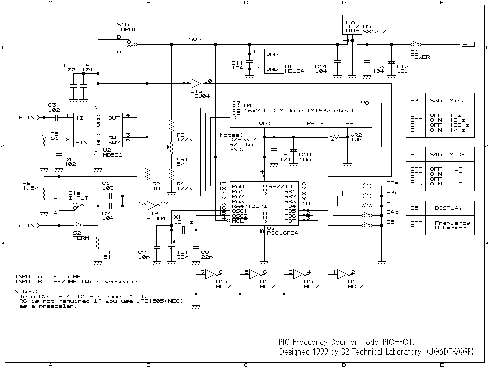
frequency counter
This design aims to function as a high-accuracy frequency and time measurement instrument, surpassing the precision of standard spectrum analyzers and oscilloscopes. The factors affecting measurement precision include time base stability, instrument definition, trigger precision, and internal noise. Both frequency and cycle are interdependent, and thus the error calculation methods for frequency measurements and periodic errors are consistent. Measurement errors can be categorized into two types: random errors, which arise from noise and unpredictable factors, and fixed errors, which are due to the measurement method, instrument setup, or inherent instrument characteristics. Different manufacturers may have distinct algorithms for addressing these errors.
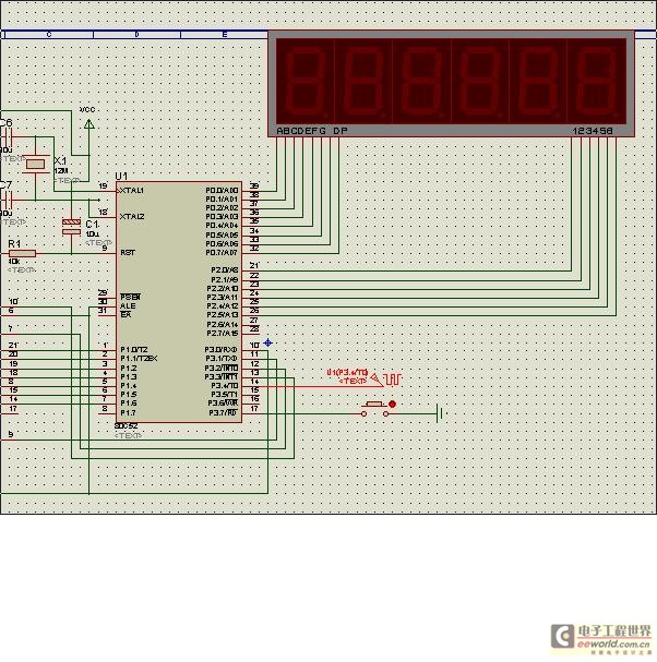
The circuit utilizes the timer/counter functions T0 and T1 of the AT89S51 microcontroller to measure the frequency of the input signal. The frequency results are displayed using eight dynamic nixie tubes. The design requires the ability to accurately count signal frequencies ranging from 0 to 250 kHz, with a maximum counting error not exceeding 1 Hz. The operating modes of timers T0 and T1 are configured to facilitate continuous counting of the input frequency signal.
The schematic design includes the following components and considerations:
1. **Microcontroller (AT89S51)**: This microcontroller serves as the core processing unit, responsible for handling input signals and executing counting algorithms.
2. **Timer/Counter Configuration**: Timers T0 and T1 are set up in appropriate modes to ensure accurate frequency counting. T0 operates in a counting state, continuously processing the input frequency.
3. **Signal Conditioning Circuit**: For frequencies below 100 Hz, a signal conditioning circuit is implemented to convert the input signal into a rectangular wave. This ensures that the width of the output wave corresponds to the cycle of the input signal, allowing for effective counting.
4. **Display Interface**: Eight dynamic nixie tubes are integrated to provide a visual representation of the measured frequency. The display is updated in real-time to reflect the current frequency count.
5. **Error Handling and Calibration**: The design incorporates mechanisms for error detection and calibration to ensure measurement accuracy. This includes algorithms to compensate for both random and fixed errors, enhancing the reliability of the measurements.
6. **Power Supply and Grounding**: Adequate power supply considerations and grounding techniques are implemented to minimize noise and ensure stable operation of the circuit.
Overall, this design synthesis provides a robust framework for high-accuracy frequency measurement, addressing both the technical requirements of frequency response time and measurement precision.This design synthesis has considered the survey accuracy of the frequency and measured the requirement of response time. For example it is 3 significant digits to look on the measuring result of the frequency as, require, at this moment if the frequency of the signal to be measured is 1 Hz, it must be greater than 1 000 s to count the gate width.
In order to give consideration to the survey accuracy of the frequency and requirement for measuring response time, divide measuring the work into two kinds of methods: 1 When at the time of frequency of the signal to be measured> 100 Hz, fix /counter constitute counter, on a basis of machine cycle, produce, count gate from software, width count gate>, at the 1 s, satisfiable the intersection of frequency and for 3 significant digit measuring result; 2 As the frequency <100 Hz of the signal to be measured, timing / counter constitutes the timer, by turning the signal to be measured into a rectangular wave for the processing circuitry of frequency counter, the rectangular wave width equals the cycle of the signal to be measured. Make and count the gate with the rectangular wave at this Read more This design synthesis has considered the survey accuracy of the frequency and measured the requirement of response time.
For example it is 3 significant digits to look on the measuring result of the frequency as, require, at this moment if the frequency of the signal to be measured is 1 Hz, it must be greater than 1 000 s to count the gate width. In order to give consideration to the survey accuracy of the frequency and requirement for measuring response time, divide measuring the work into two kinds of methods: 1 When at the time of frequency of the signal to be measured> 100 Hz, fix /counter constitute counter, on a basis of machine cycle, produce, count gate from software, width count gate>, at the 1 s, satisfiable the intersection of frequency and for 3 significant digit measuring result; 2 As the frequency <100 Hz of the signal to be measured, timing / counter constitutes the timer, by turning the signal to be measured into a rectangular wave for the processing circuitry of frequency counter, the rectangular wave width equals the cycle of the signal to be measured.
Make and count the gate with the rectangular wave at this Read more As high-accuracy frequency and time test instrument, it is tested that the precision is higher than ordinary spectrum analyzer and ondoscope in the frequency counter, so test the calculation of the precision is paid close attention to. Influence and test the precision, the factor of producing the error in other words is numerous, and the most master factor is stability of time base, definition within the instrument, touch off precision and internal noise etc.
among them. Frequency and cycle are both as reciprocally, so in the test of the frequency counter, frequency and periodic error algorithmic method are uniform. From testing the production of the error to say that mainly there are two kinds, one is random error, one kind is a fixed error.
The random error, mainly because such as the noise or error that some random factors produce, it is very difficult to dispel. The fixed error is mainly the error that because test method, instrument are set up or the instrument characteristic causes.
Different apparatus manufacturers all have one`s own algorithmic method about the error, very much the same, this text expounds the Read more Utilize the regular counter functions of T0, T1 of AT89S51 one-chip computer, to finish counting the frequency to the signal input, the frequency result counted reveals through 8 dynamic nixie tubes. Require that be able to count the signal frequency of 0- 250KHZ accurately, the counting error does not exceed 1HZ.
1. Timing / counter T0 and T1 operating mode is set up, pursued knowingly, T0 is the work under counting the state, go on, count to frequency signal that input, to 🔗 External reference
Related Circuits
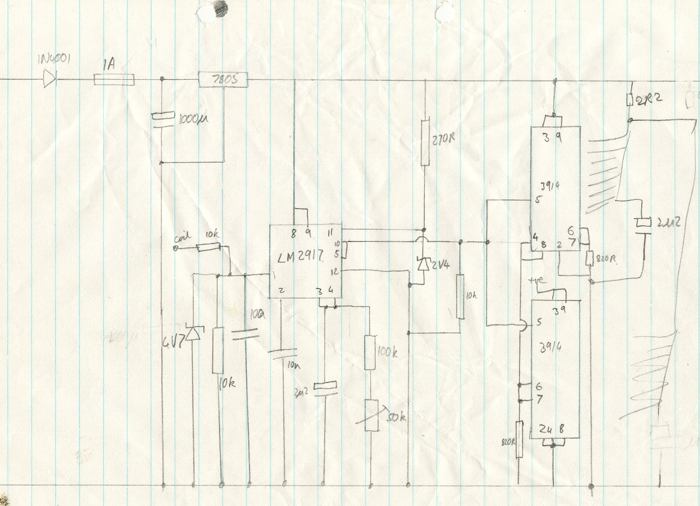
This circuit utilizes an LM2917 frequency-to-voltage converter. The input is connected to the low voltage side of the ignition coil, with various components designed to produce a full-scale output at 6000 RPM, corresponding to 12000 ignition pulses per minute,...
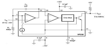
The circuit diagram of a voltage-to-frequency (V/F) converter is presented, designed to handle negative input voltage. It employs the VFC32 voltage-to-frequency converter, which is commonly utilized in various applications. The V/F converter circuit is essential in converting an analog voltage...
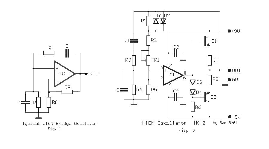
The circuit was designed to create an electronic oscillator known as the Wien Bridge Oscillator, which can be used for the generation of low-frequency sine waves. The Wien Bridge Oscillator is a type of electronic oscillator that generates sine waves....
This is an image Schematic. No Description available. The provided input indicates that there is an image schematic without any accompanying descriptive details. In the absence of specific schematics or circuit details, it is essential to consider the typical...
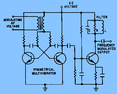
The circuit depicted in figure 2-6 and discussed in previous sections serves illustrative purposes only and is not practical in real-world applications. Nevertheless, the fundamental principle involved—the variation in reactance of an oscillator circuit in response to modulating voltage—represents...
Thomas Edison developed the incandescent light bulb, which operated from a 110-volt DC source. The primary drawback of DC power was that it could only be distributed over short distances without needing to be regenerated. In the early 1900s,...