
Methods of frequency modulation

The described circuit utilizes a Hartley oscillator, a common configuration for generating high-frequency signals. The oscillator comprises an inductor (L1) and a capacitor (C1) forming the tank circuit, which determines the fundamental frequency of oscillation. The inclusion of the reactance tube, functioning as a variable reactance element, allows for dynamic frequency modulation. The reactance tube's configuration enables it to either increase or decrease the effective reactance of the tank circuit, thus modulating the frequency of the oscillator based on the control voltage applied to its grid.
The operational principle hinges on the phase relationship between the applied voltage and the resulting current. When the modulating voltage is applied to the grid of the reactance tube, it alters the tube's behavior, causing it to present either capacitive or inductive reactance. This change in reactance directly affects the oscillation frequency, enabling frequency modulation. The design ensures that the reactance tube's influence is significant enough to modify the oscillator's frequency without introducing excessive distortion or instability.
The choice of components, particularly the values of R1 and C7, is crucial for ensuring that the circuit operates within its intended parameters. By maintaining R1 at a value much greater than the capacitive reactance of C7, the circuit achieves a high degree of linearity in its response to the modulating voltage. This careful balancing of component values allows the oscillator to maintain stable operation while effectively responding to frequency modulation signals.
Overall, this configuration exemplifies a practical application of reactance modulation in oscillator circuits, highlighting the interplay between circuit components and their collective impact on frequency stability and modulation effectiveness.The circuit shown earlier in figure 2-6 and the discussion in previous paragraphs were for illustrative purposes only. In reality, such a circuit would not be practical. However, the basic principle involved (the change in reactance of an oscillator circuit in accordance with the modulating voltage) constitutes one of the methods of developing a f
In direct modulation, an oscillator is frequency modulated by a REACTANCE TUBE that is in parallel (SHUNT) with the oscillator tank circuit. (The terms "shunt" or "shunting" will be used in this module to mean the same as "parallel" or "to place in parallel with" components.
) This is illustrated in figure 2-11. The oscillator is a conventional Hartley circuit with the reactance-tube circuit in parallel with the tank circuit of the oscillator tube. The reactance tube is an ordinary pentode. It is made to act either capacitively or inductively; that is, its grid is excited with a voltage which either leads or lags the oscillator voltage by 90 degrees.
When the reactance tube is connected across the tank circuit with no modulating voltage applied, it will affect the frequency of the oscillator. The voltage across the oscillator tank circuit (L1 and C1) is also in parallel with the series network of R1 and C7.
This voltage causes a current flow through R1 and C7. If R1 is at least five times larger than the capacitive reactance of C7, this branch of the circuit will be essentially resistive. Voltage E1, which is across C7, will lag current by 90 degrees. E1 is applied to the control grid of reactance tube V1. This changes plate current (Ip), which essentially flows only through the LC tank circuit. This is because the value of R1 is high compared to the impedance of the tank circuit. 🔗 External reference
Related Circuits
The LM2889 is designed to interface audio and video signals to the antenna terminals of a television receiver. It consists of a sound subcarrier oscillator, an FM modulator, a video clamp, and RF oscillators and modulators for two low-VHF...
The circuit was designed to create a low-cost frequency meter that will cover the range of 1 Hz to 1 MHz with a digital indication using three 7-segment displays. The frequency meter circuit operates by measuring the frequency of an...
The issue with sound cards is that they typically bandpass their input signals, making it challenging to record signals below 20Hz. Two potential solutions exist. The first involves modifying the sound card to eliminate the high-pass filter that blocks...
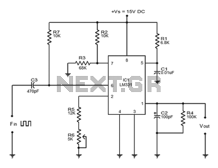
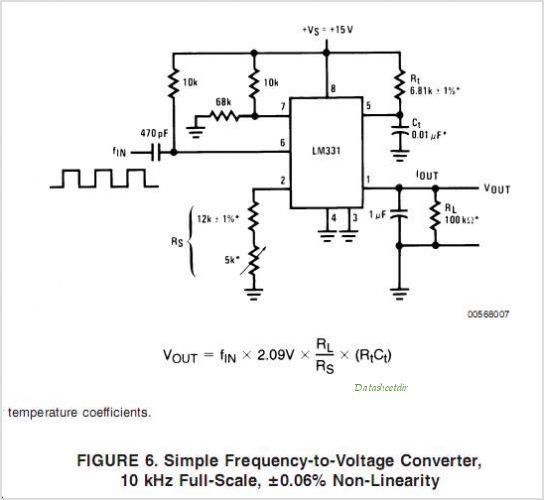
The LM331 is a precision voltage-to-frequency converter developed by National Semiconductors. This integrated circuit (IC) has various applications, including analog-to-digital conversion, long-term integration, voltage-to-frequency conversion, and frequency-to-voltage conversion. Its wide dynamic range and excellent linearity make it suitable for...
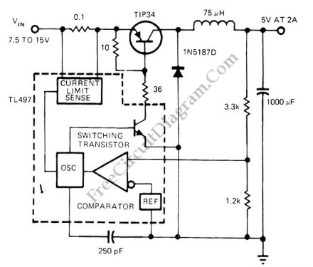
Switching voltage regulator utilizing the TL497 integrated circuit, achieving up to 75% efficiency. The output voltage is 5V, while the input voltage ranges from 7.5V to 15V. The TL497 is a versatile integrated circuit designed for use in switching voltage...
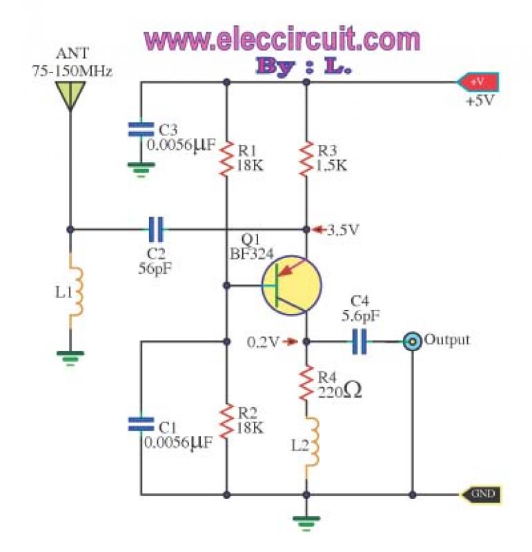
This is a wideband high-frequency amplifier circuit designed for a frequency range between 75-150 MHz. It utilizes a PNP transistor amplifier to enhance signal strength before it reaches the receiver of devices such as phones, FM radios, or amateur...