
1 KHz Frequency Wien Bridge Oscillator
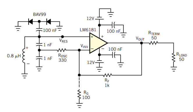
The Wien Bridge Oscillator is a type of electronic oscillator that generates sine waves. It is based on a bridge circuit that includes resistors and capacitors arranged in a specific configuration to produce a stable oscillation. The fundamental principle of the Wien Bridge Oscillator relies on the balance of the bridge circuit, which is achieved when the gain of the amplifier matches the attenuation of the feedback network.
The circuit typically consists of an operational amplifier (op-amp) configured in a feedback loop with two resistors and two capacitors. The resistors are usually arranged in a way that allows for the adjustment of the frequency of oscillation. The relationship between the resistors and capacitors determines the frequency of the output sine wave, which can be calculated using the formula:
\[ f = \frac{1}{2\pi R_1 C_1} \]
where \( R_1 \) and \( C_1 \) are the values of the resistors and capacitors in the feedback network.
To ensure stable oscillation, the gain of the op-amp must be controlled, which is often achieved using a thermistor or a light-dependent resistor (LDR) in the feedback path. This component adjusts the gain dynamically, compensating for variations in amplitude and ensuring that the oscillation remains stable without distortion.
The output of the Wien Bridge Oscillator is a low-frequency sine wave, making it suitable for applications such as audio signal generation, function generators, and testing equipment. The oscillator can be fine-tuned by adjusting the resistor and capacitor values, allowing for a wide range of frequencies to be produced.
In summary, the Wien Bridge Oscillator is a versatile and widely used circuit for generating sine waves, characterized by its simple design and ability to produce stable low-frequency oscillations.The circuit was designed to create an electronic oscillator known as Wien Bridge Oscillator which can be used for the creation of low frequency sine wave.. 🔗 External reference
Related Circuits
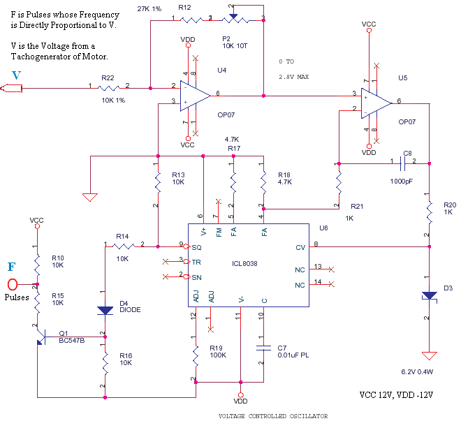
This is a small circuit designed to drive an impact counter, with the central component being the ICL8038. The circuit is intended for use with a motor that drives a conveyor, which includes a feedback mechanism known as a...
A field effect transistor amplifier features a fixed bias input source with feedback, resulting in very high input impedance and low capacitance. It drives a field effect transistor or emitter follower, despite having a very low output impedance, utilizing...
A 2N366 is configured as an audio feedback oscillator using an audio transformer. Adjust R1 for proper operation and the desired audio note. The circuit utilizes a 2N366 transistor, which is a general-purpose NPN transistor, serving as the primary active...
A current-feedback amplifier is a well-known component with many uses. Its basic block diagram shows that its input stage is a voltage follower in practice, a symmetrical emitter follower. The configuration samples the output current, converts it to voltage...
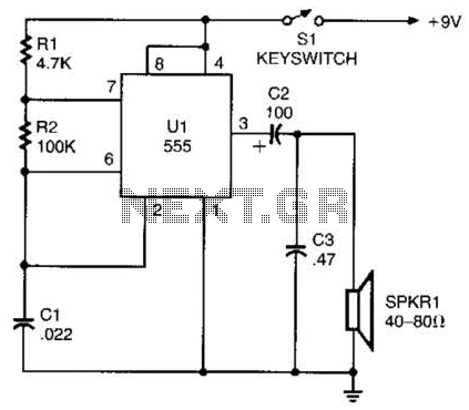
A 555 timer configured as an astable multivibrator is used in this circuit to generate an audio note. The capacitance value can be changed to vary the audio note as desired. The circuit utilizes a 555 timer IC, which...
The circuit depicted in view (D) satisfies all three criteria for an oscillator: (1) amplification, (2) a frequency-determining device (fdd), and (3) regenerative feedback. This schematic represents a tuned-base oscillator, as the fdd is located in the base circuit....
Warning: include(partials/cookie-banner.php): Failed to open stream: Permission denied in /var/www/html/nextgr/view-circuit.php on line 713
Warning: include(): Failed opening 'partials/cookie-banner.php' for inclusion (include_path='.:/usr/share/php') in /var/www/html/nextgr/view-circuit.php on line 713