
Frequency counter Divider schematic

The divider circuit employs the HC4052 analog multiplexer, which allows for the selection of different division factors based on the CONTROL input. This configuration provides flexibility in signal processing, enabling the output to be adjusted according to the user's requirements. The HC4052 is a dual 4-channel multiplexer that can route analog signals, making it suitable for this application where the division factor needs to be selected dynamically.
The AC04 operational amplifier is utilized to drive three indication LEDs, which serve as visual indicators of the current division setting. This feature enhances user interaction by providing immediate feedback on the operational status of the divider circuit. The buffering capability of the AC04 ensures that the signal integrity is maintained, preventing distortion that could arise from loading effects.
In addition, the HC390 dual binary counter is incorporated into the design. This component contains two independent counters capable of dividing input signals by 2 and 5. By combining these counters, the circuit can effectively achieve division by 10, offering a versatile solution for various signal processing applications. The combination of these components allows for a robust divider design that is both efficient and user-friendly, suitable for a range of electronic applications.The divider design is pretty self-explanatory. One can choose between division by 1, 10 or 100 or no output (tied low) using the CONTROL input connected to the analog multiplexer HC4052. AC04are used to drive 3 indication LEDs as well as to buffer the signal. A single HC390 includes 2 divider by 2 and 5 which can be combined as 2 dividers by 10. 🔗 External reference
Related Circuits
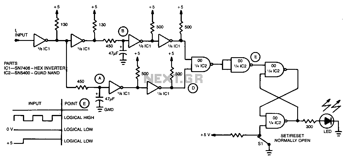
A simple inverter and NAND gate can be connected to create a highly compact and reliable digital frequency detector. This circuit is capable of detecting frequencies up to 3 MHz with a 50% duty cycle. When a frequency appears...
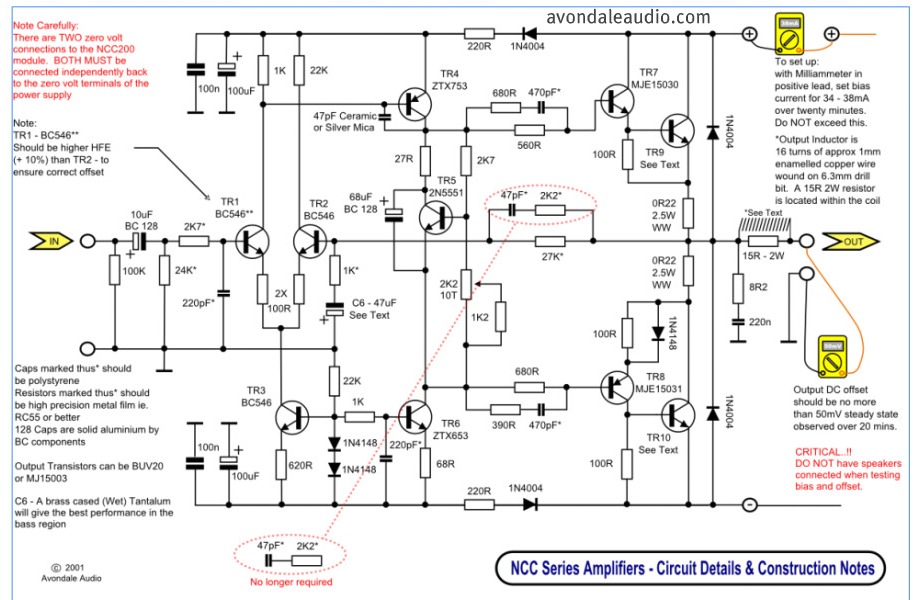
This is a simple circuit that features high-performance power amplifiers. The power amplifier is available as a PCB, along with a complete list of components. The described circuit utilizes high-performance power amplifiers, which are essential for applications requiring significant signal...
The timer is utilized in a conventional setup, with the exception that the timing resistor has been substituted with a current source derived from the operational amplifier DA1 (741). This modification enables the achievement of excellent linearity, exceeding 3%....
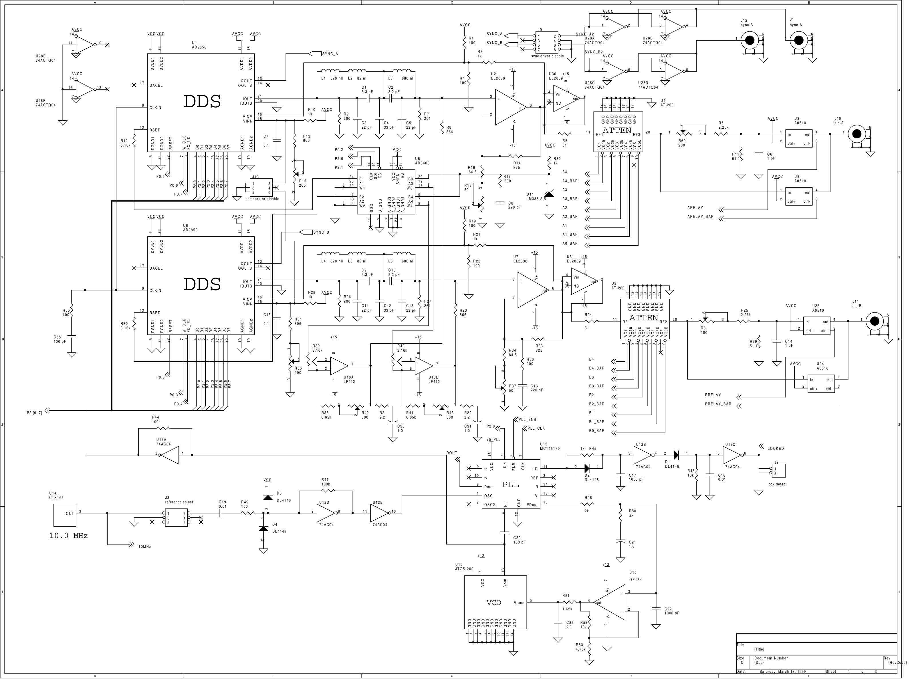
This instrument is a one or two channel frequency synthesizer. DC to 35 MHz frequency with 0.1 Hz resolution. +16 to -48 dBm signal level with 0.1 dB resolution. adjustable phase between the 2 channels with 11.25 degree resolution....
The RF engineer often needs an instrument that can reliably and quickly check a low-frequency quartz crystal unit. However, such equipment is challenging to find, and engineers frequently refer to electronic circuit handbooks for schematics that can perform this...
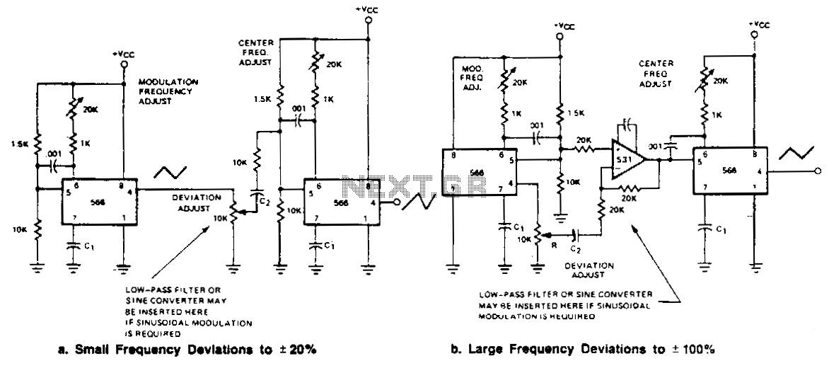
Two FM generators are presented for low frequency applications with a center frequency of less than 0.5 MHz. Each generator utilizes a 566 function generator as a modulation generator and a second 566 as the carrier generator. Capacitor C1...