
Simple voltage to frequency converter
The described circuit employs a timer in a standard configuration, integrating a current source from an operational amplifier (op-amp) to enhance performance characteristics. The op-amp DA1 (741) functions as a current source, replacing the traditional timing resistor. This design choice is significant as it improves linearity, ensuring that the frequency response remains consistent across the specified input voltage range.
The circuit operates by taking an input voltage that varies from 0 to 5 V. As this input voltage changes, the output frequency correspondingly shifts from 0 Hz to a maximum of 21 kHz. The linear relationship between the input voltage and output frequency is quantified by the factor of 4.2 kHz/V, indicating that for every volt increase in input, the output frequency increases by 4.2 kHz.
This configuration is particularly useful in applications requiring precise frequency modulation based on variable input voltages. The choice of the 741 op-amp is a common practice due to its favorable characteristics, such as low offset voltage and good frequency response, making it suitable for this type of timing application. The circuit’s ability to maintain linearity better than 3% further underscores its reliability for precision timing tasks.
In summary, the integration of a current source from the op-amp instead of a resistor not only enhances the linearity of the output frequency but also allows for a broader and more controlled frequency range, which can be critical in various electronic applications.The timer is used in typical configuration, except that the timing resistor is replaced with the current source based on the op-amp DA1 (741). This solution allowed to obtain a good linearity (better than 3%). With the value of components used in this circuit the output frequency will increase linearly from 0 to 21kHz while the input voltage incre
ases from 0 to 5 V (the input voltage controls the output frequency with the relationship 4. 2 kHz/V). 🔗 External reference
Related Circuits
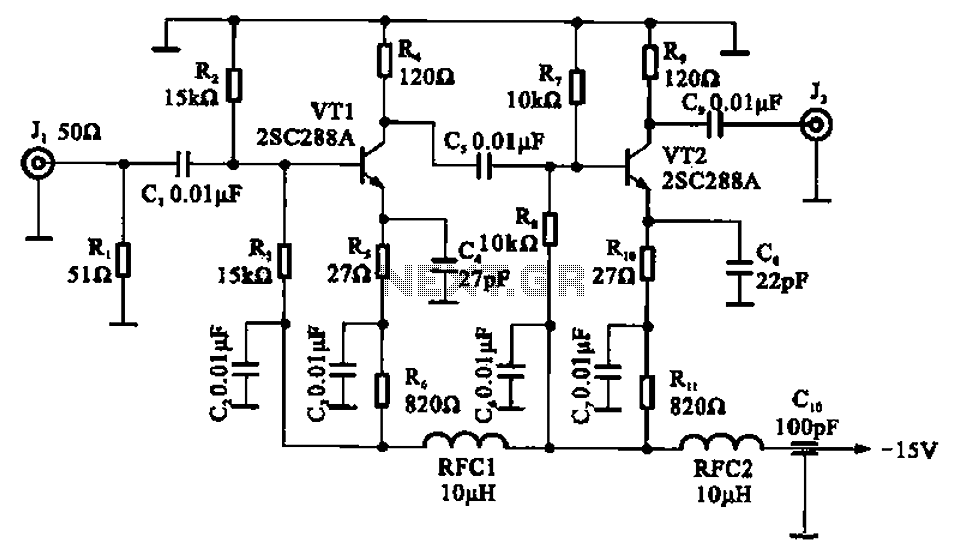
A wideband high-frequency amplifier circuit is presented, utilizing resistance and capacitance coupling in a common emitter configuration to amplify high-frequency signals. When a high-frequency signal with an input impedance of 50 ohms is applied to the amplifier through a...
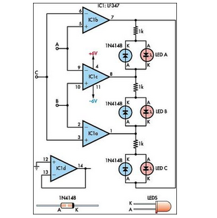
This circuit indicates which of three voltages in the range from approximately -4V to +4V at points A, B, and C is the highest by illuminating one of three indicators. The circuit is designed to compare three input voltages, labeled...
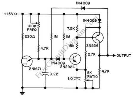
A discrete oscillator circuit illustrated in the schematic diagram below is a variable duty cycle and variable frequency oscillator, which can be utilized to generate various output waveforms. The discrete oscillator circuit is designed to produce oscillations with adjustable frequency...
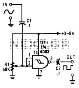
This circuit converts a sine wave into a square wave. It consists of a single 2-input NAND Schmitt trigger configured as an inverter, with an adjustable trigger level at its input. As the input voltage exceeds the gate's trigger...
STMicroelectronics introduces the STV0288, its latest DVB and DIRECTV QPSK digital receiver, which adds blind scan capability and DiSEqC 2.0 to the industry-leading STV0299 and provides a cost reduction path for new products. The STV0288 is a sophisticated digital receiver...

The 2N4391 features a low ON resistance of 30 ohms and a high OFF impedance of less than 0 pF when in the off state. With appropriate layout and an optimal switch configuration, the stated performance can be easily...