
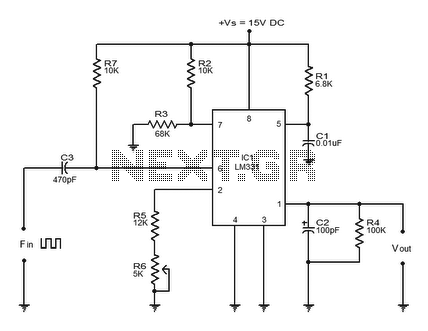
FREQUENCY COUNTER PREAMP
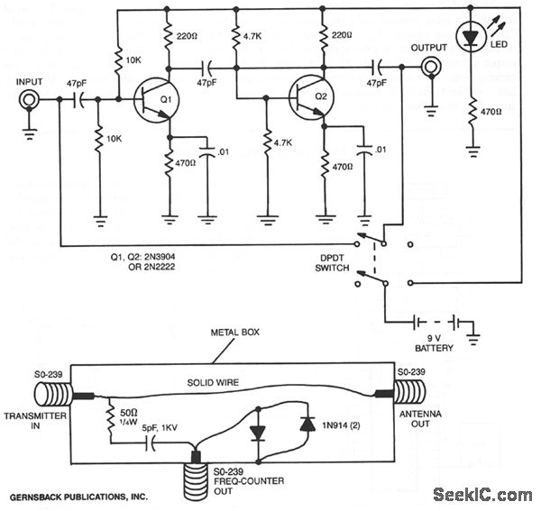
The described circuit employs a preamplifier designed to enhance the sensitivity of signal detection in various applications, particularly in radio frequency environments. The use of shielded cable minimizes electromagnetic interference, ensuring that the signals remain intact during transmission to the counter. The DPDT (Double Pole Double Throw) switch allows for flexible operation, enabling users to bypass the preamplifier when amplification is not required, thus conserving power and reducing noise.
In scenarios where the preamplifier is utilized as a receiver, its ability to increase signal strength by 6 S-units at 30 MHz demonstrates its effectiveness in improving the clarity and reliability of received signals. This characteristic is particularly advantageous in environments with weak signal conditions, allowing for better performance in communication systems.
The inclusion of a line tap in the circuit design facilitates direct frequency measurement from the transmitter output. With a simple configuration comprising two diodes, a resistor, and a capacitor, the line tap is capable of sampling low-amplitude signals without significantly affecting the main transmission line. This feature is crucial for monitoring and analyzing the frequency output of transmitters, making it suitable for applications in amateur radio and other RF communication systems.
The circuit is designed to accommodate a wide range of transmitter output power, from 1 W to 250 W, ensuring versatility in various operational contexts. This adaptability is essential for users who may need to interface with different equipment while maintaining accurate frequency measurements. Overall, this preamplifier and line tap circuit represents a robust solution for enhancing signal detection and measurement in electronic communication applications.By using the preamplifier with a short length of shielded cable and clip leads, signals that generally could not generate a readout, generate precise and stable readouts on the counter. The DPDT switch is used to bypass the circuit when amplification is not needed. The preamplifier can also be used for other purposes. For example, the unit was als o tested as a receiver preamplifier and increased received signal strength about 6 S-units at 30 MHz. A line tap can be used to measure the frequency directly at the output of a transmitter. The entire circuit for that consists of two diodes, one resistor, and one capacitor. The line tap simply picks a low-amplitude signal for measurement by the frequency counter. The tap can be connected to transmitters with an output power of between 1 and 250 W. 🔗 External reference
Related Circuits
This circuit is capable of measuring frequencies up to 40 MHz. To achieve accurate measurements, it is essential to divide both the oscillator frequency and the input frequency by four. Consequently, the time interval between measurements is extended to...

Phase noise is a critical performance parameter of frequency synthesizers for wireless applications. RF system designers of phase-modulated cellular systems, such as PHS, GSM, and IS-54, require low noise local oscillator (L.O.) or frequency synthesizer blocks. This document describes...
This is a design for a low noise microphone preamplifier, which is ideally suited to low impedance (600 Ohm nominal) microphones. One limitation is that it is not balanced, which is not a problem in a home recording environment,...
The circuit is straightforward, yet it delivers impressive results. Tr1 operates in grounded base mode, providing a low impedance input through its emitter. The specified values ensure proper operation from a 9V power supply. When using different voltage levels,...
Converter circuits are commonly utilized in various applications, and there are several types available. A simple frequency-to-voltage converter circuit uses the IC LM331, which is essentially a precision voltage-to-frequency converter. This IC has numerous applications, and in this instance,...
A NE555 integrated circuit (IC) is utilized for the design of a variable low-frequency oscillator, and a schematic is provided. The NE555 timer IC is a versatile and widely used device in various electronic applications, particularly in generating precise timing...