
Frequency crystal oscillator circuit diagram of 10kHz-150kHz

In this circuit configuration, the transistor acts as a variable impedance component that influences the resonant frequency of the oscillator circuit. The primary function of capacitor C1 is to determine the timing characteristics of the oscillator, while the transistor allows for dynamic adjustment of the output frequency. By altering the capacitance value through C1, the resonant frequency can be finely tuned within the specified range, which is critical for applications requiring precise frequency control.
The choice of the transistor type is essential, as it must be capable of handling the required frequency range and load conditions. Commonly used transistors for such applications include bipolar junction transistors (BJTs) or field-effect transistors (FETs), depending on the desired characteristics of the oscillator circuit. The transistor's biasing must be carefully designed to ensure optimal operation within the desired frequency range while minimizing distortion and maintaining stability.
The relationship between the transistor, load capacitance, and C1 is vital for achieving the desired oscillator performance. When the load capacitance is approximately equal to the capacitance of C1, the circuit can achieve better resonance, leading to a more stable output frequency. The approximation of value X indicates that while a theoretical value can be calculated, real-world variations in component values and operating conditions may lead to deviations from this approximation.
Overall, the described oscillator circuit is a versatile design that can be employed in various applications, such as signal generation, frequency modulation, and timing circuits, where precise frequency adjustment is necessary. Proper component selection and circuit design are crucial for achieving the desired performance characteristics.And a transistor in series with C1 can be used to adjust the oscillator output frequency. Frequency may be in the range of 20pF to 0.01 F change, or as the tuning capacitor, th e transistor and the load capacitance approximately equal. The value of X is an approximation, for most circuits and frequency can be changed.
Related Circuits
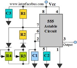
The astable multivibrator circuit lacks a stable state. In the absence of an external signal, the internal transistors alternately switch between cutoff and saturation at a frequency determined by the RC time constants of the coupling circuits. Therefore, an...
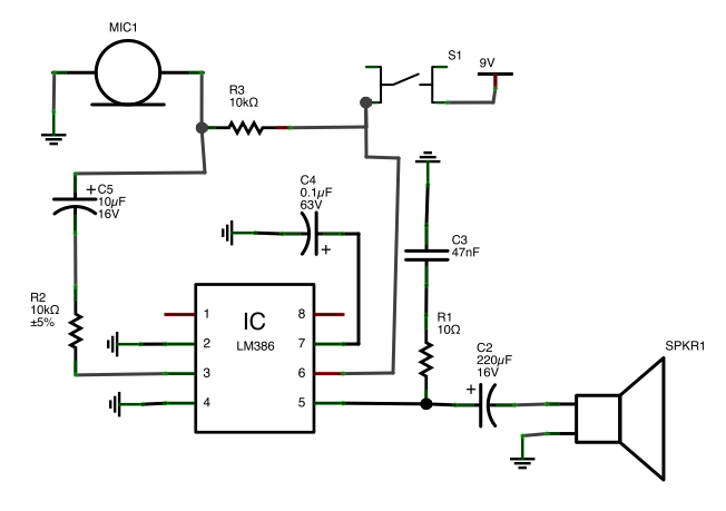
A button is utilized as a push-to-talk switch. While it generally functions correctly, there is a significant delay of approximately five seconds before any audio output is heard upon pressing the button. The described circuit involves a push-to-talk switch, which...
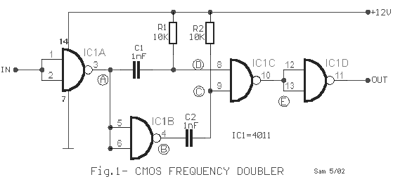
This frequency doubler utilizes a CMOS quad two-input NAND gate package, specifically the 4011 type. The core of the frequency doubler includes an inverter (IC1B) along with two differentiating networks composed of resistors (R1, R2) and capacitors (C1, C2)....
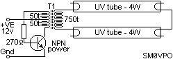
There is no PCB since there are no components to mount on one. The object was to create a source of ultraviolet light as fast as possible. The UV tubes I bought from a lighting shop for use with...
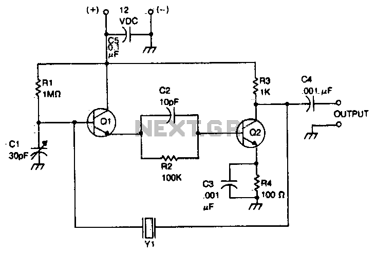
The crystal is positioned between the collector of the output stage and the base of the input stage. The oscillation frequency can be accurately adjusted using the trimmer capacitor CI. This circuit operates within a frequency range of 500...
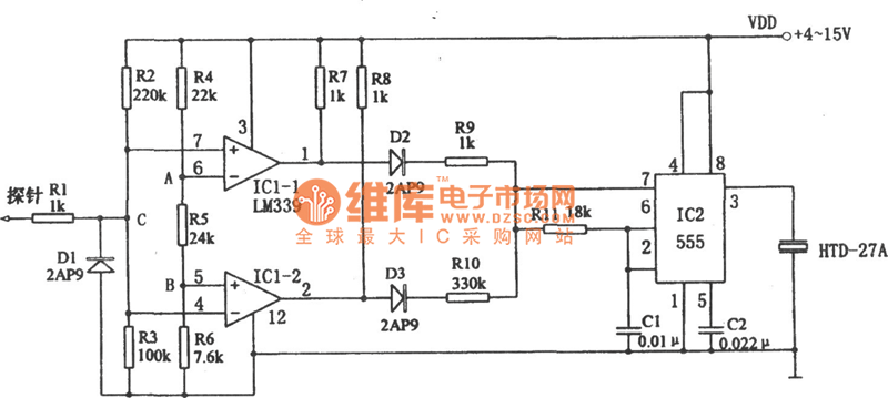
The above picture illustrates an audio logic level probe circuit, which consists of a voltage comparator, a multivibrator, and piezoelectric ceramics (HTD). The multivibrator and piezoelectric components together form the audio circuit, which operates at an audio frequency to...