
Parallel-mode aperiodic crystal oscillator

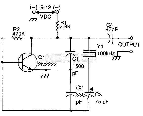
The described circuit utilizes a crystal oscillator configuration, where the crystal serves as a frequency-determining element. In this setup, the crystal is connected between the output stage's collector and the input stage's base, which allows for stable oscillation. The precise frequency of oscillation is achieved through the use of a trimmer capacitor, CI, which can be adjusted to fine-tune the frequency output.
The operational frequency range of the circuit is from 500 kHz to 10 MHz, making it suitable for various applications requiring medium-frequency oscillation. To extend the frequency range downward to 100 kHz, modifications to the circuit components are necessary. By increasing the capacitance of CI to 75 pF and adjusting the capacitor C2 to 22 pF, the circuit can be adapted to operate effectively at lower frequencies.
It is important to note that the selection of the crystal and the values of the capacitors are critical to achieving the desired frequency stability and performance. The design must ensure that the components are rated appropriately for the intended frequency range and that the overall layout minimizes parasitic capacitance and inductance, which can affect the oscillation characteristics. Proper attention to these details will ensure reliable operation and optimal performance of the oscillator circuit across its specified frequency range.The crystal is placed between the collector of the output stage and the base of the input stage. The frequency of oscillation can be set to a precise value with trimmer capacitor CI. The range of operation for this circuit is 500 kHz to 10 MHz Extend the range downward (100 kHz) by increasing the value of CI to 75 pF and increasing the value of C2 to 22pF.
Related Circuits
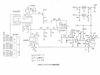
This MOT's LSI is highly suitable for designing VFOs in ham radios, featuring a 4-digit BCD preset counter with a range from 3 to 3999. It also includes a standard crystal frequency oscillator and preset dividers. The input nodes...
The beat frequency oscillator (BFO) is essential for receiving continuous wave (CW) signals. Since CW signals lack an audio modulation component, it is necessary to introduce one. The functions of the RF amplifier, mixer, local oscillator, and IF amplifier...

A simple circuit that can generate an inverted square wave similar to the one used by the inventor on his function generator. To construct a circuit that produces an inverted square wave, a basic approach involves using a 555 timer...
This circuit is commonly utilized by amateur radio operators, shortwave listeners, and various users of shortwave receivers to calibrate the dial pointer. The oscillator functions at a fundamental frequency of 100 kHz, with its harmonics employed to identify specific...
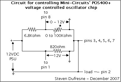
This is a UHF oscillator circuit designed to utilize the Mini-Circuits POS-400+ voltage-controlled oscillator chip. By applying a voltage between 0 to 12V on pin 8, it produces a sine wave output ranging from 200MHz to 380MHz on pin...
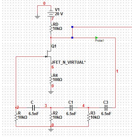
Assistance is required for the design of a FET-based Wien bridge oscillator and its simulation using PSpice. Any suggestions would be appreciated. The Wien bridge oscillator is a type of electronic oscillator that generates sine waves. It employs a bridge...