
Frequency divider
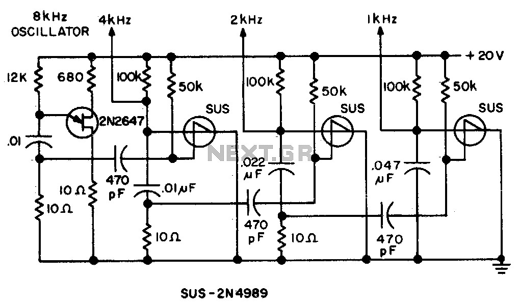
This circuit is designed to mitigate unwanted spikes that occur in the center of a sawtooth waveform. The sawtooth wave, characterized by its linear rise and abrupt fall, is commonly used in various applications such as signal generation and waveform synthesis. However, spikes can distort the intended signal, leading to inaccuracies in performance.
The circuit achieves spike elimination through a triggering mechanism. This involves monitoring the sawtooth waveform and identifying the precise moment when a spike occurs. A comparator or a similar device can be employed to detect these anomalies. Once a spike is identified, a control signal is generated to modify the waveform, effectively suppressing the spike.
The design may incorporate operational amplifiers to enhance the detection sensitivity and speed of response. Additionally, filtering components such as capacitors and resistors can be included to smooth out the waveform further, ensuring that the output remains clean and stable.
In summary, this circuit provides a robust solution for spike elimination in sawtooth waves, enhancing the quality and reliability of the signal for various electronic applications.Spikes in the center of a sawtooth wave are eliminated in this circuit by triggering at. 🔗 External reference
Related Circuits
The MK50398 is one modern decimal counter up/down of six tens, with control of screen LED of seven segments and flip-flop of storage. Counter it can measure additive and abstractively. The IC MK50398 is ideal for manufacture frequency counter...
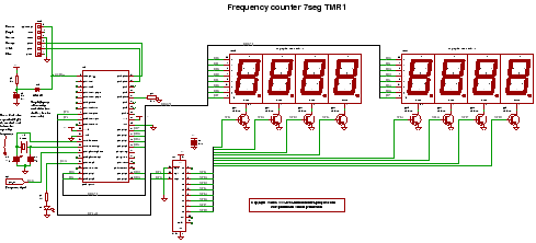
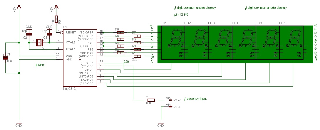
C code for a frequency counter circuit operating up to approximately 50 MHz, utilizing a multiplexed seven-segment display and employing Timer 1 to count the edges of the input signal. The frequency counter circuit described operates effectively within the range...
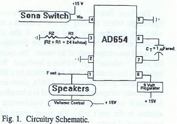
Assistance is required for converting high frequency to low frequency and vice versa. A project involving a sensor is currently in progress, and the schematic is provided below. The conversion of high frequency signals to low frequency signals, as well...
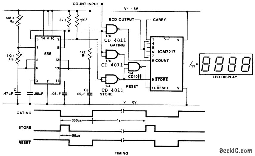
This is an inexpensive frequency counter and tachometer circuit. It utilizes a 556 dual timer to generate the gating, not-store, and not-reset signals for an ICM7217 counter. One timer operates as an astable multivibrator using resistors RA, RB, and...
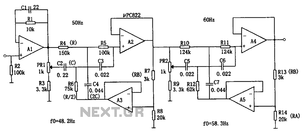
The circuit depicted in the figure is a frequency power supply noise filter circuit, specifically a double-T filter. It is designed to amplify weak signals, such as those from sensors, while filtering out mixed 50Hz (or 60Hz) power supply...
This frequency counter is designed to display the frequency from a frequency generator with an analog setting. It is a straightforward counter that can be utilized as a module within a box containing a frequency generator. The device measures...