
Frequency Meter
The frequency meter sends to address $02 (the RS232 to RF Data Channel receive address) and receives address $03 (which is coded as $18 in the firmware because of the position of the address within the header byte).
Firmware
This firmware was a combination of the firmware from two projects, with the irrelevant parts removed. There are several assembler warnings of registers being assigned more than once - don't worry about it, there aren't any conflicts but it made hooking the two pieces of code a little easier and made the resulting file a little easier to read doing it this way.
Here is the Assembler source file. In case it's helpful, here is the hex file.
At power-on, a greeting and menu are displayed. Individual readings are taken whenever the "R" key or return key are pressed.
Variations
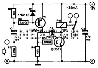
A low battery indicator would be a nice improvement so that the terminal would be alerted when a low battery was detected. Additionally, an LED could be added as a power-on indicator. By the way, the one I built takes 16 mA while transmitting and 12 mA while looking for a signal.
The low speed of the data channel is noticeable as the greeting and menu are tediously written on the terminal screen. The low speed of the data channel is not apparent when taking measurements of 1 second or longer. For shorter period measurements (10 ms and 100 ms), the effects of the terminal's receiver's recovery time are apparent. The effect is that the further the frequency meter is from the RS-232 to 100 MHz adapter, the more likely the first characters (carriage return and line feed) will be lost when the frequency meter sends the results of the measurement, which come more quickly after a short time base measurement than a long one. A delay should be added to prevent transmission from starting within a given time after a transmission was observed - in this case, about 300 ms (forever to an AVR processor, but not a long time from the standpoint of the receiver).
The frequency meter circuit utilizes the AT90S2313 microcontroller, which is responsible for processing the input frequency signals and managing the communication with the RS-232 to RF adapter. The circuit includes a frequency counting mechanism that utilizes a timer to capture the number of pulses within the specified time bases. The maximum input frequency of 4 MHz allows for a wide range of applications, while the counting capability of up to 65535 provides sufficient resolution for most frequency measurement tasks.
The design incorporates a selectable time base feature that can be adjusted through user input via the RF link. This flexibility is crucial for accommodating various measurement scenarios, allowing the user to select between 10 ms, 100 ms, 1 second, 10 seconds, and 100 seconds intervals based on their requirements.
To enhance the robustness of the frequency meter, a 5-volt zener diode is recommended to be connected from pin 9 of the AT90S2313 to ground. This addition serves to protect the microcontroller's input from potential damage due to electrostatic discharge events, which can occur during operation.
The firmware running on the AT90S2313 is a streamlined version derived from previous projects, ensuring efficiency and clarity. At power-up, the user is greeted with a menu that facilitates easy navigation through the measurement functions. The firmware also handles the communication protocol, utilizing specific addresses for sending and receiving data, which is critical for the operation of the RS-232 to RF data channel.
In terms of power consumption, the frequency meter operates at 16 mA during transmission and 12 mA while idle, which is efficient for battery-operated applications. The implementation of a low battery indicator and a power-on LED would further enhance user experience by providing visual feedback regarding the operational status of the device.
Overall, the design and implementation of the frequency meter offer a practical solution for frequency measurement applications, combining effective hardware design with efficient firmware to deliver reliable performance.This basically the frequency meter section of the frequency meter/pulse generator based on the AT90S2313 described elsewhere on this site, combined with the 100 MHz RF interface described in the page about the RS-232 to 100 MHz RF desktop channel adapter. Built and align this is the same manner as the 100 MHz RF desktop channel adapter. The frequency meter has a maximum input frequency of 4 Mhz and counts up to 65535. Time bases of 10 ms, 100 ms, 1 second, 10 seconds, and 100 seconds are selectable from the keyboard via the RF link.
I would suggest adding a 5 volt zener from pin 9 of the AT90S2313 to ground to reduce chances of damage to the input from electrostatic discharges. I did not put it on the schematic because I did not build this and try it. Take a look at the frequency and pulse generator project on this web site to see how I used the reverse base-emitter junction of a transistor to accomplish the same thing because I didn't have any appropriate zeners at the time of the project.
The frequency meter sends to address $02 (the RS232 to RF Data Channel receive address) and receives address $03 (which is coded as $18 in the firmware because of the position of the address within the header byte). Firmware This firmware was a combination of the firmware from two projects, with the irrelevant parts removed.
There are several assembler warnings of registers being assigned more than once -don't worry about it, there aren't any conflicts but it made hooking the two pieces of code a little easier and made the resulting file a little easier to read doing it this way. Here is the Assembler source file. In case its helpful, here is the hex file At power-on a greeting and menu is displayed. Individual readings are taken whenever the "R" key or return key are pressed. Variations A low battery indicator would be a nice improvement so that the terminal would be alerted when a low battery was detected.
Additionally an LED could be added as a power-on indicator. By the way, the one I built takes 16 ma while transmitting and 12 ma while looking for a signal. The low speed of the data channel is noticeable as the greeting and menu are tediously written on the terminal screen. The low speed of the data channel is not apparent when taking measurements of 1 second or longer. For shorter period measurements (10 ms and 100 ms) the effects of the terminal's receiver's recovery time are apparent.
The effect is that the further the frequency meter is from the RS-232 to 100 MHz adapter, the more likely the first characters (carriage return and line feed) will be lost when the frequency meter sends the results of the measurement, which come more quickly after a short time base measurement than a long one. A delay should be added to prevent transmission from starting within a given time after a transmission was observed -in this case, about 300 ms (forever to an AVR processor, but not a long time from the standpoint of the receiver).
🔗 External reference
Related Circuits
A NE555 integrated circuit (IC) is utilized for the design of a variable low-frequency oscillator, and a schematic is provided. The NE555 timer IC is a versatile and widely used device in various electronic applications, particularly in generating precise timing...
A VOX is a voice-operated switch that is often used as a substitute for the press-to-talk switch on a microphone. This VOX can be connected to almost any audio equipment that has a socket for an external loudspeaker. The...
These parameters are expected with an approximately 50% square wave up to frequencies of several MHz, and symmetric sine waves at higher frequencies. The primary limitation is based on the maximum clocking rate specification for the MM74HC6040 ripple counter...
This is an easy-to-build yet highly accurate digital voltmeter designed as a panel meter. It can be utilized in DC power supplies or any application requiring precise voltage readings. The circuit uses the CL7107 Analog to Digital Converter (ADC)...

This circuit is a simple LED voltmeter designed to monitor the charge level of lead-acid or tubular batteries. The terminal voltage of the battery is displayed through four LED indicators. The nominal terminal voltage for a fully charged lead-acid...
This design circuit is used to activate circuitry and an analog meter for sensitive DC current measurements. A subsequent inquiry raised the possibility of measuring AC microamperes, which inspired the idea for this circuit. The circuit is designed to facilitate...