
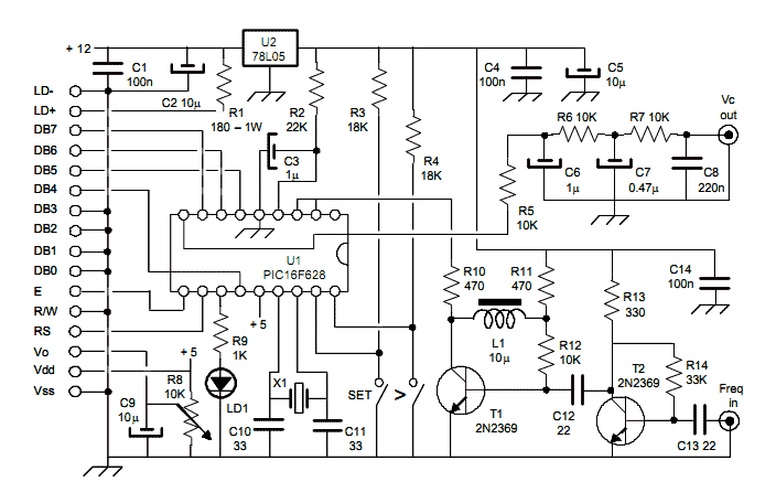
330 MHz prescaler for AVR frequency meter
Regardless of how the signal is routed, it must first pass through an input protection network, which includes two Schottky diodes and a Zener clamp. The 1N5711 Schottky diodes prevent the input signal from going more than a Schottky diode drop below ground or above the power supply. Schottky diodes are used due to their lower voltage drop compared to the PN protection diodes in the CMOS integrated circuit they are intended to protect, allowing them to draw more current from excessive input voltages than the input protection diodes in the integrated circuits.
The two 1N5226 Zener diodes in series prevent the power supply from rising above 6.6 volts in case the input is accidentally connected to a low impedance source that is higher than 5 volts. A 47 Ohm resistor limits the input current in case of excessive voltage being applied to the inputs.
The input of the frequency meter requires a full 5-volt CMOS logic swing, and the prescaler's output is less than 1 volt peak-to-peak. Therefore, when the prescaler is switched into the circuit, the signal goes through the prescaler, then the preamp, which drives the frequency meter through the Schmitt trigger buffers.
The MCT10280 prescaler can be set to divide by 80, 40, 20, or 10, depending on which pins are tied to the power supply. A division factor of 10 is selected as it suffices for the intended application, simplifying mental calculations for the meter reading. However, a notable issue with the MCT10280 is that if it does not receive an adequate input, the output can be very noisy, resulting in erroneous counts in the couple MHz range on the frequency meter. This noise occurs when the signal amplitude or frequency is too low, hence the prescaler is intended for use with inputs ranging from 10 MHz to 300 MHz.
Regardless of the division factor, the signal must pass through the preamp. In the preamp stage, a 2N5485 N-channel FET is configured as a source follower, providing high input impedance to the input signal while driving the subsequent stage, a 2N3663 limiting amplifier, with a low impedance signal, yielding high AC gain.
The output from the 2N3663 consists of clean square waves with fast rise and fall times. When interfacing with the 74HCT02 input on the frequency meter, care must be taken to avoid oscillation at the input. To mitigate this risk, the signal is routed through a 74HCT14 Schmitt trigger. The cable carrying the signal has an impedance of approximately 150 ohms, necessitating the use of two 300-ohm resistors in parallel to minimize ringing at the frequency meter end of the cable. No termination is applied at the frequency meter end, as it would diminish the signal amplitude below the CMOS thresholds.
Power for the entire circuit is supplied via the cable and is regulated by a 78L05 voltage regulator, ensuring stable operation across the various components involved in the frequency measurement process.These parameters are expected with an approximately 50% square wave up to frequencies of seveal MHz, and symmetric sine waves at higher frequencies. The primary limitation is based on the maximum clocking rate specification for the MM74HC6040 ripple counter in use in the Slightly More Serious Frequency Meter project.
Selection of faster parts and careful circuit layout can extend the upper limit of the useful frequency range. The lower frequency imit is the lowest sine wave input frequency for the MCT12080 at which the input of the MCT10290 does not osccilate.
Schmitt trigger buffer that then sends the signal on to the counter. Regardless of how the signal is routed, it must first pass through an input protection network, which includes two schottky diodes and a zener clamp. The 1N5711 schottky diodes prevent the input signal from going more than a schottky diode drop below ground or above the power supply.
I used Schottky diodes because they have a lower voltage drop than the PN protection diodes on the CMOS integrated circuit they are intended to protect, and as such, they will draw much more of the current from excessive input voltages than the input protection diodes in the integrated circuits. The two 1N5226 zener diodes in series prevents the power supply from rising above 6.6 volts in case the input is accidentally connected to a low impedance source that is higher than 5 volts.
The 47 Ohm resistor limits the input current in case of excessive voltage being applied to the inputs. The input of the frequency meter requires a full 5 volt CMOS logic swing, and the prescaler's output is less than 1 volt peak-to-peak, so the prescaler, when switched into the circuit, the signal goes through the prescaler, then the preamp, and the preamp drives the frequency meter through the Schmidt trigger buffers.
The MCT10280 prescaler can be set to divide by 80, 40, 20, or 10, as a function of which pins are tied to the power supply. I set this one to divide by 10 since it is adequate for my needs, and the mental calculation of multiplying the meter reading by 10 is not taxing.
One problem with the MCT10280 is that if it doesn't have an adequate input, the output is very noisy, which shows up as counts in the couple MHz range on the frequency meter. This noise shows up if the signal amplitude the signal frequency is too low. For this reason, I only intend to use the prescaler with inputs between 10 MHz and 300 MHz. Whether the signal is divided by ten or not, it must pass through the preamp. In the Preamp, a 2N5485 N-channel FET is connected as a source follower. This provides a high input impedance to the input signal and drives the next stage, the 2N3663 limiting amplifier with a nice low impedance signal.
This results in high AC gain. DC buffer Signals from the 2N3663 are nice, clean square waves with fast rise and fall times, and when driving the 74HCT02 input on the frequency meter, could result in the input of the 74HCT02 oscillating. To prevent this, the signal is passed through a 74HCT14 Schmitt trigger. The signal conductor in the cable has an impedance of about 150 ohms, so it is driven through two 300 ohm resistors in parallel to keep the ringing on the frequency meter end of the cable to a tolerable level.
There is no termination on the frequency meter end of the cable because terminating it would reduce the amplitude of the signal below the CMOS thresholds. Power for all the circuit comes through the cable and is regulated by the 78L05 regulator. 🔗 External reference
Related Circuits
This is a schematic and block diagram of a 2-MHz frequency counter. It employs an LSI counter/display driver, an LCD readout, and several logic chips for timebase and timing pulse circuitry. Transistors Q2 and Q3 form a signal input...
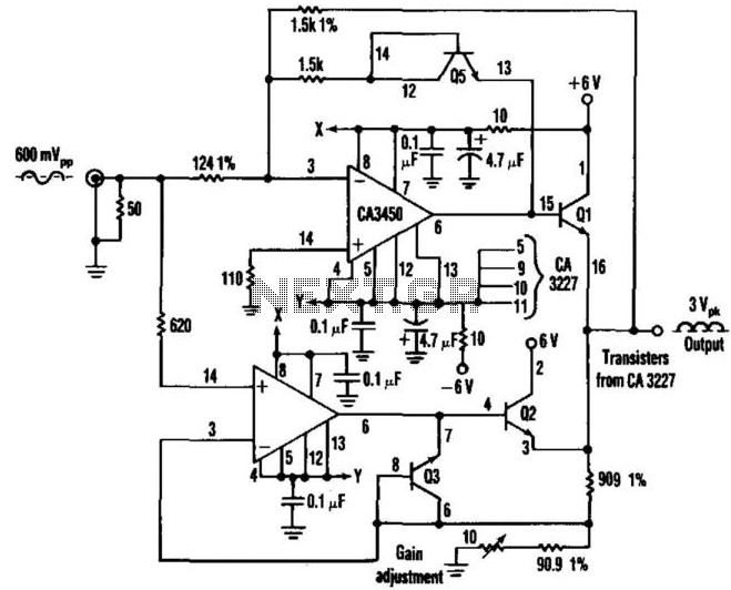
This circuit employs two CA3450 operational amplifiers and a CA3227 transistor array to achieve accurate full-wave rectification of signals up to 10 MHz. Two of the CA3227 transistors are responsible for driving the output, while the other two are...
The principle of operation is quite simple, a counter measures the VFO frequency, the new reading is compared with the previously stored value and an adequate correction is applied consequently. This process has been implemented in the past using...

Most analog multimeters can measure resistance across a wide range of values; however, they can be inconvenient due to their reverse reading scale, which is also non-linear. This can lead to poor accuracy, especially at the high-value end of...
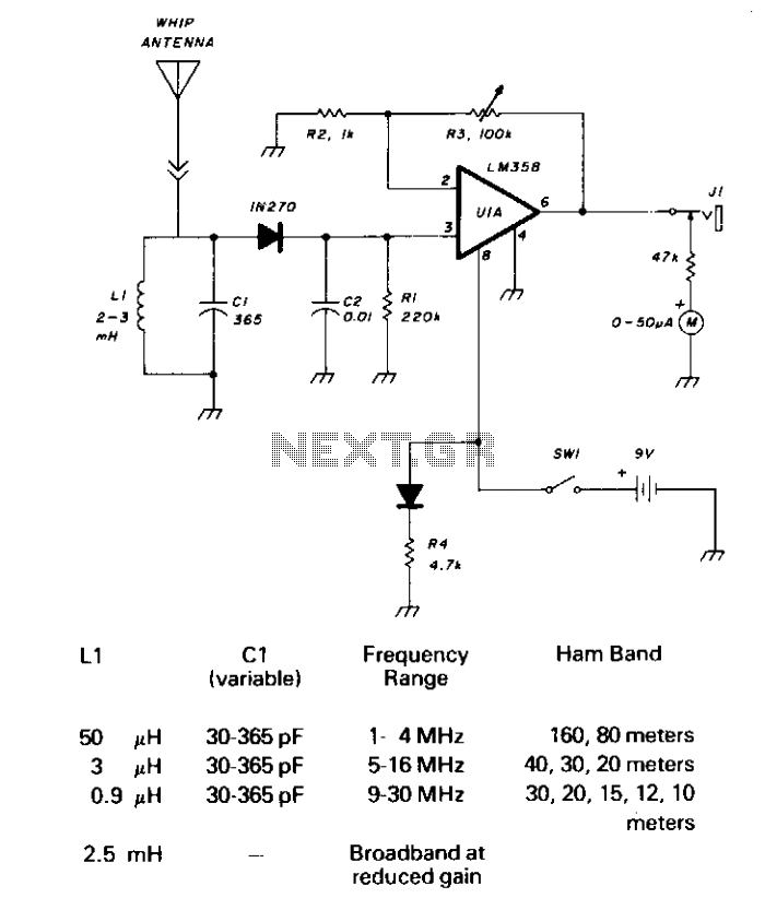
CI and LI resonate on the 1750-meter band, with coverage from 150 kHz to 500 kHz. LI can be slug-tuned for 160 to 190 kHz coverage alone, or a 2.5 mH choke can be used for LI, if desired,...
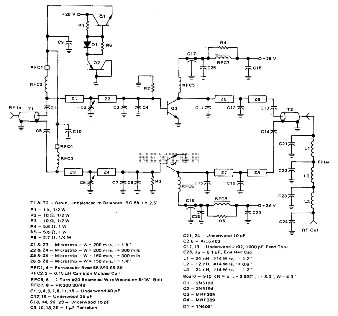
This 100-watt linear amplifier can be built using two MRF309 transistors in a push-pull configuration, requiring only 16 watts of drive power within the frequency range of 420 to 450 MHz. It operates from a 28-volt supply and achieves...