
AC-DC Microammeter Circuit
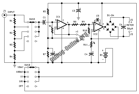
The circuit is designed to facilitate precise measurements of both DC and AC microamperes using an analog meter. The core of the design involves a sensitive operational amplifier configured to amplify the current signal, which can then be displayed on a calibrated analog meter.
For DC measurements, a shunt resistor is employed to convert the current to a measurable voltage drop. The operational amplifier takes this voltage and amplifies it to a level suitable for the analog meter, ensuring that even small currents can be accurately measured. The configuration allows for a wide range of sensitivity, making it suitable for delicate applications.
To extend the functionality to AC microamperes, the circuit incorporates a rectifier stage. This stage converts the AC signal into a corresponding DC voltage that can be processed by the operational amplifier. A capacitor is included to filter out high-frequency noise, ensuring that only the desired signal is amplified.
The analog meter is calibrated to read both AC and DC measurements, allowing for easy interpretation of results. Additionally, the circuit may include a switch that allows the user to toggle between AC and DC measurement modes, enhancing versatility.
Overall, this circuit design offers a robust solution for measuring low-level currents in both AC and DC formats, making it an invaluable tool in various electronic applications.Here s a design circuit that is used to active circuitry and an analog meter to make sensitive DC current measurements. A reader subsequently asked if it could measure AC microamperes and that is what spawned the idea. This is the figure of the circu .. 🔗 External reference
Related Circuits
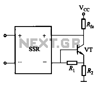
A DC solid-state relay (DC-SSR) driving a high-power load circuit is illustrated in (a) below; the high-power load driving circuit is depicted in (b) below. The DC solid-state relay (DC-SSR) serves as a crucial component in controlling high-power loads, providing...
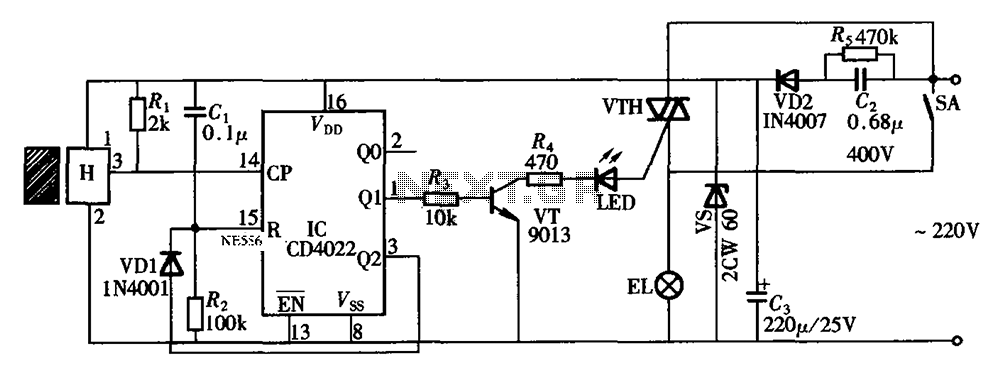
The circuit illustrated in the figure depicts an automatic bathroom light switch system. When the door is opened, the light is activated, illuminating the space. Conversely, when the door is opened again, the light turns off. The circuit comprises...
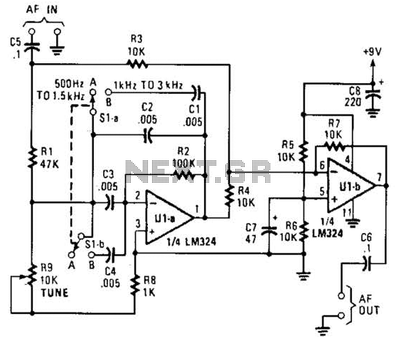
The notch filter can be integrated into nearly any receiver to attenuate a specific frequency by over 30 dB. This filter is particularly useful for diminishing heterodynes and whistles. A notch filter, also known as a band-stop filter, is designed...

The circuit illustrated in the figure features an automatic voltage regulator (T) that utilizes a servo motor to ensure a constant output voltage. The transistors used are VT1 and VT2 (3DK9C, with a range of 65 to 85) and...
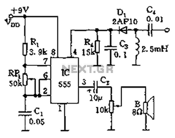
The circuit features a 555 timer integrated circuit along with components R1, RP1, C1, and others, which together form an audio oscillator. The frequency of the oscillator is determined by the formula f = 1.44 / ((R1 + 2...
This project involves outdoor LED solar garden lights, which function as an automatic garden lighting system utilizing a light-dependent resistor (LDR) and a 6V/5W solar panel. During daylight hours, the internal rechargeable 6 Volt sealed lead-acid (SLA) battery is...