
Frequency Meter using PC
The described technique for measuring frequencies utilizes a combination of hardware and software components to achieve acceptable accuracy across a wide frequency range. The core of the system relies on cascaded binary counters that effectively convert high-frequency signals into manageable low-frequency signals suitable for processing by a PC. This conversion is essential as it allows for the measurement of periods of complete waves, which is the foundation for frequency calculation.
The parallel port of the PC serves as the interface for data input from the binary counters. The specific control register (379 Hex) is used to facilitate this communication, with a 25-pin D connector providing the necessary connections. The software component generates a time-interrupt at a frequency of 18.21 Hz, which acts as a reliable time-reference for measuring the time periods of the incoming signals.
Data collection occurs over a fixed time frame of approximately 54.9 milliseconds, during which the software continuously reads the control register and stores the data in an array. This array is then analyzed bit-wise, beginning with the most significant bit (MSB). The presence of a complete square wave is checked, and if identified, the time period of the wave is measured. If a full wave is not detected, the software sequentially checks the next lower bits until a wave is found or an error condition is triggered.
The lowest frequency that can be measured is effectively determined by the sampling time, with a practical lower limit set at approximately 19 Hz. Conversely, the upper frequency limit is contingent upon the configuration of the MOD counter utilized. For instance, a MOD-16 counter can handle frequencies up to approximately 20 MHz, while a MOD-10 counter is limited to about 1.9 MHz. The precision of measurements is influenced by the speed of the PC and the number of data points collected within the specified time frame, with higher precision achievable through the use of MOD-10 counters. However, this choice can impose restrictions on the upper frequency limit that can be measured, highlighting the trade-offs inherent in the design of such frequency measurement systems.Here is a simple technique for measuring frequencies over quite a wide frequency range and with acceptable accuracy limits using a PC. It follows the basic technique of measuring low frequencies, i.e. at low frequency, period is measured for a complete wave and frequency is calculated from the measured time-period.
Cascaded binary counters are used for converting the high-frequency signals into low-frequency signals. The parallel port of a computer is used for data input from binary counters. This data is used for measuring time and calculating the frequency of the signal. The block diagram shows the basic connections of the counters and parallel port pin numbers on 25-pin D connector of a PC (control register 379 Hex is used for input).
External hardware is used only for converting the higher frequency signals into low frequency signals. Thus, the major role in frequency-measurement is played by the software. The PC generates a time-interrupt at a frequency of 18.21 Hz, i.e. after every 54.92 millisecond. Software uses this time-interrupt as a time-reference. The control register of the PC`s parallel port is read and the data is stored continuously in an array for approximately 54.9 ms using a loop.
This stored data is then analysed bit-wise. Initially, the higher-order bit (MSB or the seventh-bit) of every array element is scanned for the presence of a complete square wave. If it is found, its time period is measured and if not then the second-highest order bit (sixth bit) is scanned.
This operation is performed till the third bit and if no full square wave is still found, an error message is generated which indicates that either there is an error in reading or the frequency signal is lower than 19 Hz. Lower three bits of the control register are not used. When a wave is found, along with its time-period and frequency components, its measurement precision in percentage is also calculated and displayed.
Number of data taken in 54.9 ms is also displayed. As stated above, the lower starting range is about 19 Hz. Data is read for approximately 54.9 ms. Thus, the lowest possible frequency that can be measured is 1/.0549 Hz. Lower range depends only on the sampling time and is practically fixed at 19 Hz (18.2 Hz, to be precise). Upper range depends on factors such as value of the MOD counter used and the operating frequency range of the counter IC.
If MOD-N counter is used (where N is an integer), upper limit (UL) of frequency is given by UL=19xN5 Hz. Thus for MOD 16 counters UL@20 MHz, and for MOD 10 counters [email protected] MHz. Care should be taken to ensure that this upper limit is within the operating frequency range of counter IC used.
Precision of measurement is a machine-dependent parameter. High-speed machines will have better precision compared to others. Basically, precision depends directly upon the number of data read in a standard time. Precision of measurement varies inversely as the value of MOD counter used. Precision is high when MOD 10 counters are used in place of MOD 16 counters, but this will restrict the upper limit of frequency measurement and vice-versa. 🔗 External reference
Related Circuits

This schematic illustrates a peak-reading diode voltmeter that utilizes two stages of amplification. A 100 µF capacitor is employed to provide a sufficiently large time constant, ensuring adequate meter damping. The limited differential output voltage, combined with an overdamped...
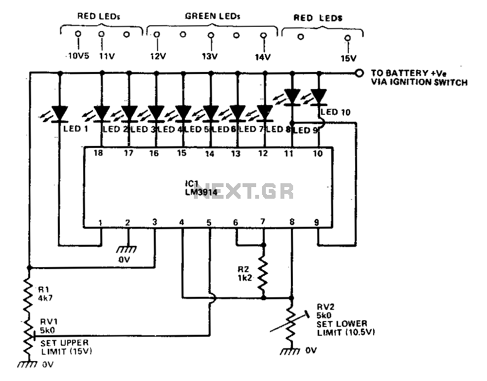
The LM39X4 functions as a LED-driving voltmeter, with its maximum and minimum readings determined by the resistor values R2 and RV2. When properly calibrated, the device operates within a 2-volt to 3-volt range but is designed to read supply...
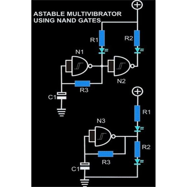
An astable multivibrator is an electronic configuration that generates continuous alternating high and low pulses from two outputs operating in tandem. The IC 4093 consists of four individual NAND gates in one package, specifically Schmitt trigger types, which provide...
The Car shows the distance a train travels on a 5 digit LCD display. The distance is indicated down to 1/100th of a mile (about the length of a 50 foot car) with an accuracy of approximately plus 2...
The digital thermometer consists of a temperature sensor, a single stabilizing circuit, a counter circuit, a decoding section, a driving circuit, and LED digital tubes among other components. It operates within a temperature range of 0 to 50 degrees...
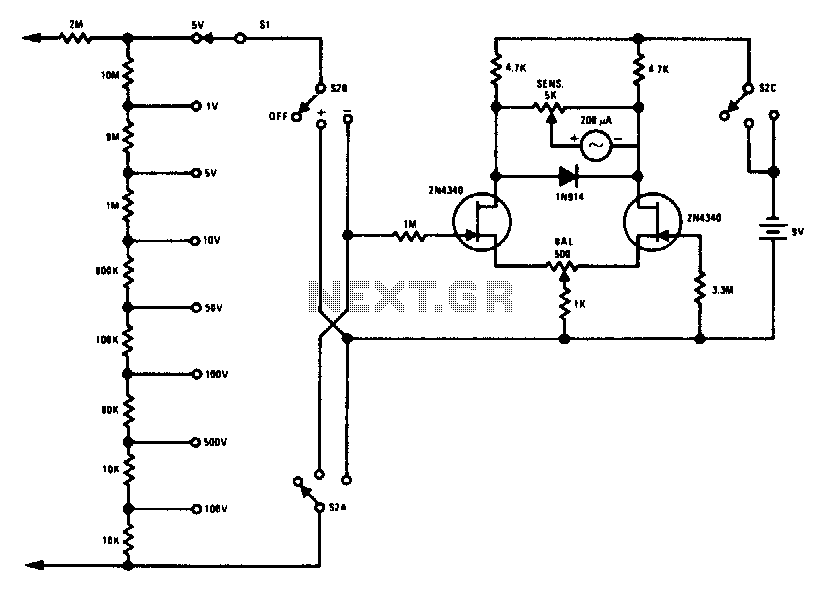
This FETVM replaces the function of the VTVM while eliminating the need for a traditional line cord. Additionally, it offers significantly improved drift rates compared to vacuum tube circuits, enabling a 0-volt full-scale range that is generally impractical with...