
Bargrapk car voltmeter
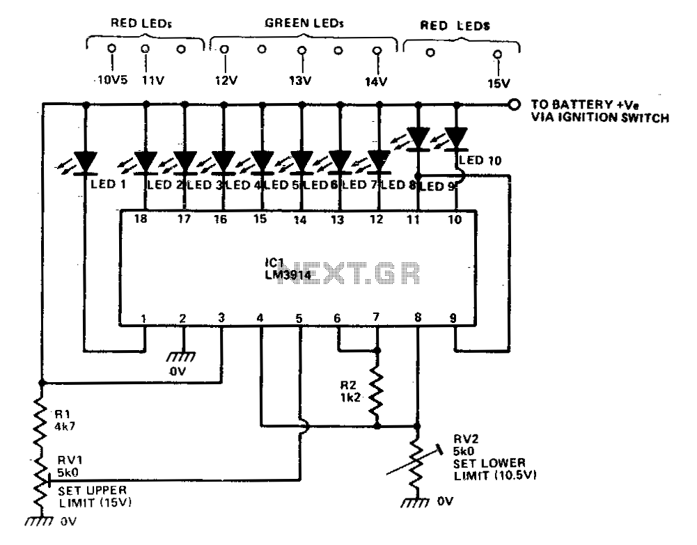
The LM39X4 is a specialized integrated circuit designed for precise voltage monitoring and display using a series of light-emitting diodes (LEDs). The operation of the LM39X4 is contingent upon the correct selection and adjustment of resistors R2 and RV2, which establish the reference voltage levels for the readout. The calibrated output range of 2 to 3 volts is achieved through careful tuning, allowing the device to accurately reflect the input voltage.
To adapt the voltmeter to a broader range of supply voltages, the potential divider formed by resistors R1 and RV1 plays a crucial role. This divider scales down the supply voltage before it is fed into the input terminal of the IC, ensuring that the IC can interpret voltage levels from 10.5 volts to 15 volts effectively. The design allows for a linear response across the specified range, enabling users to monitor voltage fluctuations with precision.
The display mechanism of the LM39X4 is particularly noteworthy. It employs a "dot" display configuration, which simplifies the user interface by illuminating only one LED at any given moment. This method not only conserves power but also provides a clear, unambiguous indication of the current voltage level. The range of LEDs corresponds to specific voltage thresholds, with LED 1 representing the lowest voltage level and LED 10 indicating the maximum.
The operational thresholds are critical for functionality; when the supply voltage drops below 10.5 volts, the system enters a low-power state, and no LEDs are illuminated, signaling an out-of-range condition. On the other hand, reaching or exceeding the upper limit of 15 volts activates LED 10, providing a visual alert that the supply voltage is at its maximum allowable level.
In conclusion, the LM39X4 is an efficient and effective solution for monitoring voltage levels within a specified range, leveraging a simple yet powerful display method and adjustable components to cater to various applications in electronic systems.The LM39X4 acts as a LED-driving vol-tometer that has its basic maximum and minimum readings determined by the values of R2 and RV2. When correctly adjusted, the unit actually covers the 2 volt to 3 volt range, but it is made to read a supply voltage span of 10-10 volts to 15 volts by interposing potential divider R1-RV1 between the supply line and the pin-5 input terminal of the IC.
The IC is configured to give a "dot" display, in which only one of the ten LEDs is illuminated at any given time If the supply voltage is below 10,5 volts none ofthe LEDs illuminate. If the supply equals or exceeds 15 volts, LED 10 illuminates. 🔗 External reference
Related Circuits
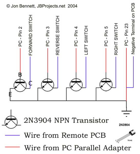
This project article was originally written in 2004 when most computers had parallel ports. This is no longer the case, so much of this information is now outdated. The Mini RC Car Project has been one of the most...
This circuit diagram represents a radio-controlled system, commonly utilized in toy car applications for children. The circuit comprises two main components: the transmitter and the receiver circuits. The transmitter circuit generates radio signals through an oscillator circuit built with...

This design circuit is for converting voltage to frequency. Typically, frequency meters are used in speed sensors, tachometers, and for measuring recurring signals. The frequency to voltage converter (FVC) can transform voltage into either a digital or analog tachometer....
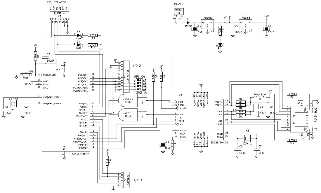
The Arduino is a simple and accessible controller platform suitable for various projects. A few months ago, an Ethernet shield was purchased for it. The Arduino platform is widely recognized for its user-friendly interface and versatility, making it a popular...
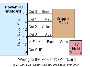
For optimal efficiency, set MAX_STEPPERS to the number of stepper motors being controlled, with a maximum limit of four. Motors are identified by indices 0, 1, 2, and 3. On the QCard, there is a trade-off between the number...

The following circuit illustrates a Car Door Keypad Electronic Circuit Diagram. Features include a lower pin-count and a cost-effective design utilizing the MC68HC908AZ60A microcontroller. The Car Door Keypad Electronic Circuit is designed to enhance vehicle security by providing a user-friendly...