
Make this Astable Multivibrator Blinker Circuit Using NAND Gates

The astable multivibrator circuit utilizing the IC 4093 is designed to produce a square wave output without requiring any external triggering. The core of the circuit is formed by the first NAND gate (N1) and its associated resistor (R3) and capacitor (C1). The resistor-capacitor (RC) combination determines the frequency of oscillation, with the values of R3 and C1 directly influencing the time period of the output waveform. The Schmitt trigger configuration of the NAND gates ensures that the output transitions are sharp and free from noise, which is critical for reliable operation.
The output of N1 oscillates between high and low states, creating a square wave signal. This output is then fed into the second NAND gate (N2), which is configured as an inverter. By shorting the input pins of N2, the circuit takes advantage of the inherent properties of NAND gates to produce an inverted version of the output from N1. The cascading of these gates allows for further manipulation of the output signal, ensuring that the desired characteristics of the waveform are maintained.
The remaining NAND gates in the IC can also be used to drive additional outputs or to modify the signal further if needed. The ability to drive LEDs directly from the outputs of the gates is a practical feature of this configuration. Each LED connected to the outputs will blink in synchronization with the oscillation frequency, providing a visual indication of the astable operation. This circuit can be employed in various applications, such as timers, flashers, or pulse generators, showcasing the versatility of the astable multivibrator design.An astable multivibrator is referred to an electronic configuration which is able to generate continuous alternate high and low pulses from a couple of outputs, operating in tandem. The IC 4093 basically consists of four individual NAND gates in one package, these are schmitt trigger types, which means the gates provide some sort of hysteresis at
their outputs in response to the input signals. In the figure, gate N1 and the associated passive parts R3 and C1 form the basic oscillator stage. The output of N1 generates alternate square wave pulses at its output having fixed mark and space ratio. The pulses generated at the output of N1 is fed to the input of the next NAND gate, which is wired up as an inverter by shorting its input pins.
Note that basically the inputs of all the gates are short circuited, thus they all behave as inverters here. The outputs of these gates are able to support LEDs directly at their outputs, so we connect a few of the LEDs at their outputs which dance or blink in response to the astable pulses.
🔗 External reference
Related Circuits
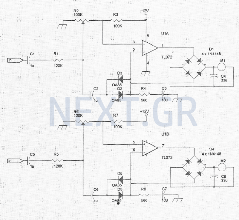
The VU meter is categorized into two types: those that use needle instruments and those that employ LED columns. A VU meter sound level meter is essential for both tube amplifiers and integrated amplifiers. Currently, there are numerous integrated...
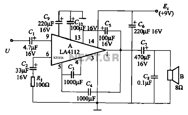
Audio power amplifier circuit utilizing the LA4112 integrated power amplifier along with additional components as shown in the figure. The audio power amplifier circuit based on the LA4112 integrated power amplifier is designed to deliver high-quality audio amplification for various...
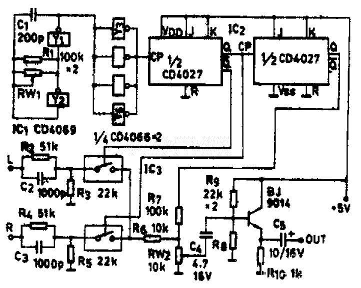
The circuit schematic diagram features IC1 (4069) and components Y1 and Y2, which together form a frequency oscillator operating at 76 kHz. Components Y3 to Y6 provide isolation and shape the output into the IC2 (CD4027) dual JK flip-flop,...
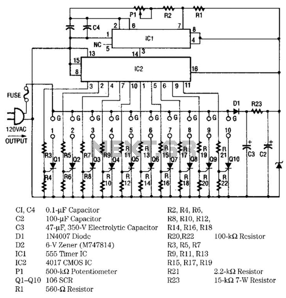
The light sequencer employs two integrated circuits (ICs) and ten silicon-controlled rectifiers (SCRs) to create an alternating current (AC) sequencer. The first IC, a 555 timer, is configured as an astable multivibrator to generate clock pulses for the second...
The diagram illustrates a timed light control switch circuit designed for outdoor advertising light boxes, street lamps, and power control applications in Mexico. This time-saving switch circuit incorporates a manual door switch for controlling the lights, addressing the common...
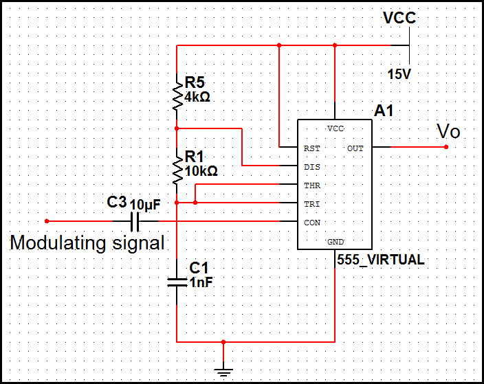
In pulse position modulation, the amplitude and width of the pulses are kept constant, while the position of each pulse with reference to the position of the reference pulse is changed according to the instantaneous sampled value of the...