
Frequency/Voltage Converter
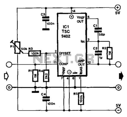
The TSC9402 integrated circuit serves dual purposes in electronic applications, functioning as both a voltage-to-frequency and frequency-to-voltage converter. This dual functionality enhances its utility in various measurement scenarios, particularly in conjunction with multimeters. The simplicity of the design allows for easy integration into existing systems, requiring minimal additional components, which streamlines the implementation process.
To utilize the TSC9402 effectively, a single calibration point is established to define the center of the measuring range, optimizing the device for the most commonly measured frequencies. This feature is particularly advantageous in applications where specific frequency ranges are of primary interest, as it allows for quick adjustments and accurate readings.
The output voltage at pin 12, designated as the amplifier output, is influenced by frequency variations. The presence of interference pulses, which can reach levels of 0.7 V, necessitates careful design considerations to ensure accurate measurements. If these interference pulses are detrimental to the multimeter's accuracy, the implementation of a simple resistor-capacitor (RC) network can provide an effective means of suppression, enhancing the reliability of the measurement.
The calculation of the output voltage, U0, through the provided formula underscores the importance of understanding the internal capacitance of the circuit. Since this value can often exceed the nominal 12 pF, users should be aware that the formula may yield relative rather than absolute output values. This characteristic emphasizes the need for careful calibration and possibly adjustment based on the specific application and components used.
Operating over a frequency range from DC to 10 kHz, the TSC9402 is particularly well-suited for applications requiring low-frequency measurements. The calculated output voltage of 3.4 V at 10 kHz illustrates the circuit's ability to provide significant voltage levels under specified conditions. Additionally, the low current draw of 1 mA ensures that the circuit can be integrated into low-power applications without compromising overall system efficiency. This combination of features makes the TSC9402 an excellent choice for a wide range of electronic measurement applications. Teledyne Semiconductor"s Type TSC9402 is a versatile IC. Not only can it convert voltage into frequency, but al so frequency into voltage. It is thus eminently suitable for use in an add-on unit for measuring frequencies with a multimeter. Only a few additional components are required for this.. Just one calibration point sets the center of the measuring range (or of that part of the range that is used most frequently). The frequency-proportional direct voltage at the output (pin 12—amp out) contains interference pulses at levels up to 0.7 V.
If these have an adverse effect on the multimeter, they can be suppressed with the aid of a simple RC network. The output voltage, U0, is calculated by: tfo=C/rei(Ci + 12 pF) R2fm Because the internal capacitance often has a greater value than the 12 pF taken here, the formula does not yield an absolute value.
The circuit has a frequency range of dc to 10 kHz. At 10 kHz, the formula gives a value of 3.4 V. The circuit draws a current of not more than 1 mA. 🔗 External reference
Related Circuits
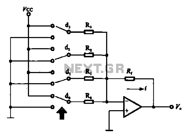
An A/D converter circuit can be represented by a simplified schematic, which illustrates a parallel type A/D converter. The term "median" refers to the number of bits in the digital signal output. The figure displays four A/D converters utilizing...
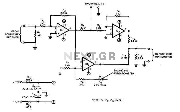
This audio converter circuit maintains 40 dB of isolation between the two halves of entry and exit of a four-line system while allowing a line connection between the two systems. A balancing potentiometer, R, adjusts the gain of the...

The 24V to 12V converter schematic is straightforward; however, it is important to ensure that all components, including transistors and integrated circuits, are adequately heat dissipated and electrically insulated from metal surfaces. The schematic diagram is derived from the...
This DIY 12V to 220V DC to AC converter utilizes a CMOS 4047 as its main component, effectively transforming 12V DC into 220V AC. The circuit design of this DC to AC converter primarily revolves around the CMOS 4047 integrated...
A step-up converter followed by an LDO regulator provides improved battery life compared to a traditional SEPIC design when powered by a single lithium-ion cell. The circuit design features a step-up (boost) converter that elevates the input voltage from a...

A step-up converter can be designed using the MAX641 integrated circuit from Maxim IC, utilizing a minimal number of electronic components. This high-voltage step-up converter project can deliver a maximum output current of up to 1A. The low battery...