
MAX641 high current step-up converter

The MAX641 integrated circuit is a highly efficient solution for applications requiring a boost in voltage. The circuit operates by drawing power from a lower voltage source and converting it to a higher voltage output, making it ideal for battery-powered devices where voltage levels may drop as the battery discharges.
The step-up converter design involves a few key components: the MAX641 IC, input and output capacitors, and the resistors that form the voltage divider. The input capacitor is essential for stabilizing the input voltage and minimizing ripple, while the output capacitor helps smooth the output voltage and maintain a steady current supply.
The voltage divider consisting of resistors R1 and R2 is crucial for setting the low battery detection threshold. When the input voltage (LB1) falls below the reference voltage of 1.31 V, the output at LBO will switch to a low state, signaling that the battery voltage is critically low. This feature is particularly useful for preventing damage to the device from under-voltage conditions and ensuring proper functionality.
In practical applications, the circuit can be implemented on a printed circuit board (PCB) layout, ensuring that all components are placed in a manner that minimizes noise and interference. Proper grounding and decoupling techniques should be employed to enhance the performance of the step-up converter. The design can be further optimized by selecting appropriate values for R1 and R2 to adjust the threshold voltage according to specific requirements.
Overall, the MAX641 step-up converter circuit provides a reliable and efficient solution for applications where increased voltage is necessary while maintaining low power consumption and simple construction.Using MAX641 integrated circuit, manufactured by Maxim IC, can be designed a very simple step-up converter using few electronic components. This step-up high voltage converter electronic projects allows a maximum output current up to 1A. Low battery voltage detector input compare LB1 with internal reference of 1. 31 V. LBO output goes in low state when the voltage at pin 1 falls below 1. 31 V. The threshold voltage for "low battery", is determined by voltage divider R1-R2. 🔗 External reference
Related Circuits
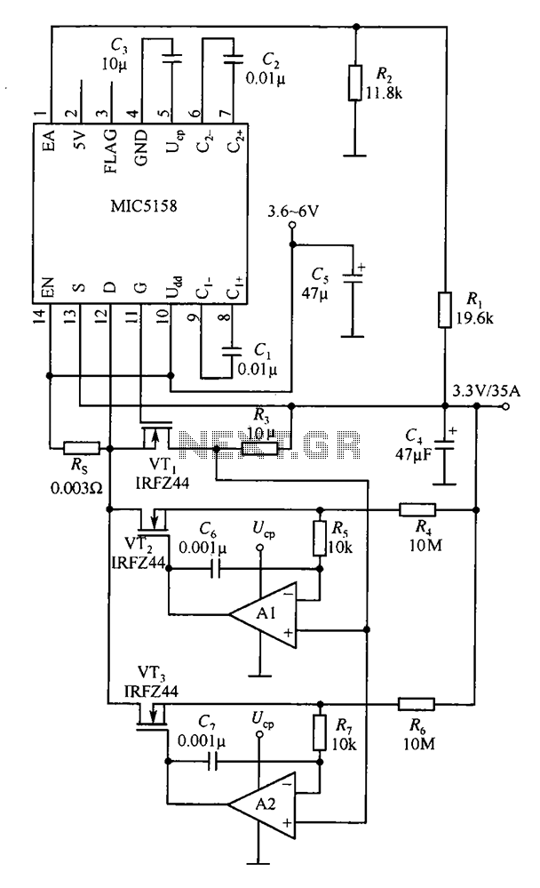
The MIC5158 is designed to manage tasks by controlling multiple external N-channel MOSFETs in parallel, which enables high current or high power output for a linear regulator circuit. This is illustrated in the accompanying figure. The operational amplifier circuit...
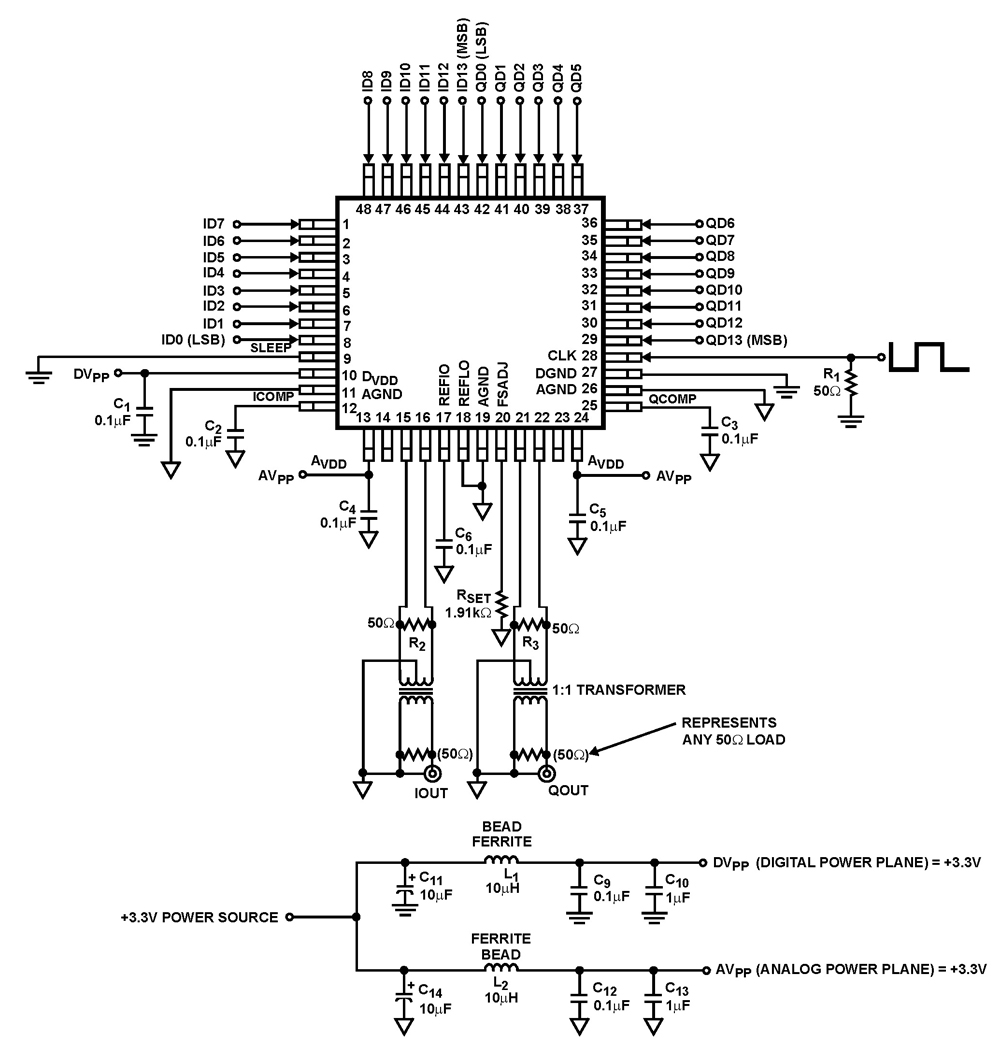
The ISL5929 is a dual 14-bit, 130/210+ MSPS (Mega Samples Per Second), CMOS, high-speed, low-power, digital-to-analog converter (DAC) designed specifically for high-performance communication systems, such as base transceiver stations utilizing 2.5G or 3G cellular protocols. The ISL5929 DAC is engineered...

In recent years, there has been a growing demand for higher reimbursement structures among music lovers and manufacturers of tube amplifiers. This is attributed to the perception that tube sound is sweeter, richer, and incomparably cleaner. However, tube amplifiers...
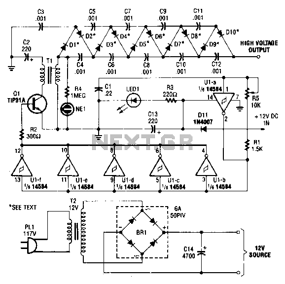
This circuit is powered by a 12-V DC power supply. The input to the circuit is amplified to generate a 10,000-V DC output. The output of the up-converter is subsequently directed into a 10-stage high-voltage multiplier to achieve a...
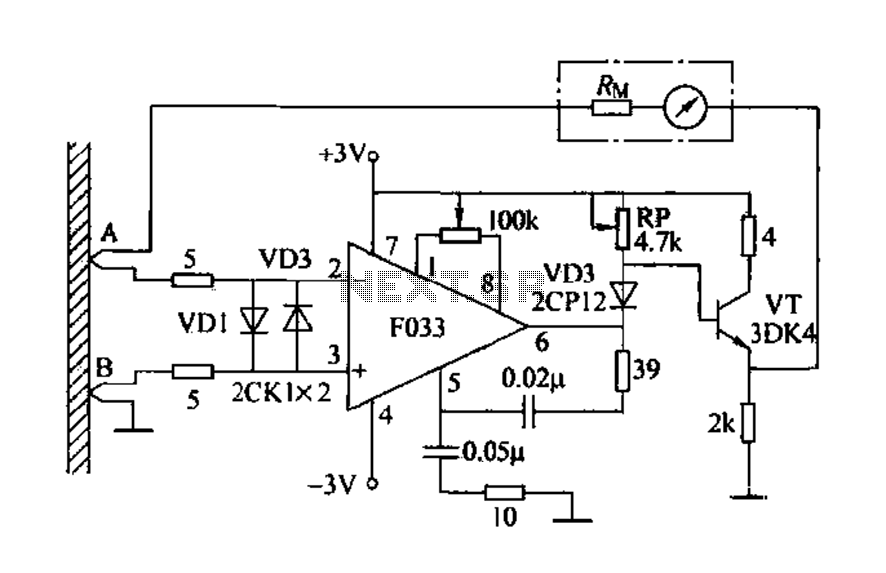
Detecting electrical equipment sometimes requires disconnecting the circuit in series for more accurate measurements of electrical current using an ammeter. However, restoring the circuit to its original state is necessary, as it can affect the normal operation of electrical...
This voltage-to-frequency converter (VFC) accepts bipolar AC inputs. For -10 to +10 V inputs, the converter produces a proportional 0 to 10 kHz output. Linearity is 0.04%, and the temperature coefficient (TC) is approximately 50 ppm/°C. To understand the...