
2 to 4 wire audio converter
The audio converter circuit is designed to facilitate the transmission of audio signals while ensuring significant isolation between the input and output stages. The 40 dB isolation implies that the circuit effectively minimizes the risk of interference and crosstalk between the two halves of the system, which is crucial in applications where audio fidelity is paramount.
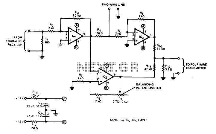
The circuit utilizes a balancing potentiometer, denoted as R, which serves to fine-tune the gain of the audio signal. This adjustment is critical for achieving optimal performance, ensuring that the output signal is neither too weak nor too strong, which could lead to distortion or clipping. The procedure for adjusting the potentiometer is straightforward; during the installation phase, a 1 kHz test tone is introduced at the input. The technician then adjusts the potentiometer until the output signal is minimized, indicating that the gain has been properly set.
In addition to the potentiometer, the circuit incorporates an 82-ohm dummy load resistor connected between the two wire terminals. This resistor plays a vital role in stabilizing the circuit by providing a consistent load, which can help prevent signal reflections and ensure that the audio signal is transmitted smoothly through the system. The use of a dummy load is particularly important in audio applications, as it helps maintain the integrity of the signal path and enhances overall performance.
Overall, this audio converter circuit is an effective solution for maintaining audio quality and isolation in multi-line systems, making it suitable for various applications in professional audio environments.This audio converter circuit maintains 40 dB of isolation between the two halves of entry and exit of a four-line son, while allowing a line connecting two son. A balancing potentiometer, R, adjusts the gain of zero lC2to crossing the inlet to the outlet. The adjustment is done in terms of work just after installation by inserting a 1 kHz tone at the entrance of four son and setting R to the minimum output signal 82-ohm dummy-load resistor is placed between two wire terminals. 🔗 External reference
Related Circuits
This circuit is intended to indicate the power output level of any audio amplifier. It is simple, portable, and displays three power levels that can be set to any desired value. IC1A is the input buffer, feeding 3 voltage...
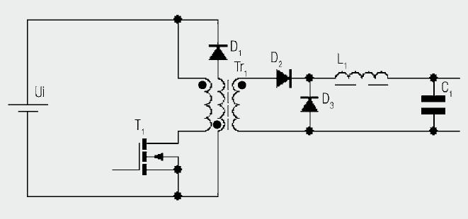
The diagram illustrates the basic construction of a forward converter. In contrast to the flyback converter, which temporarily stores energy before transferring it to the secondary side, the forward converter facilitates direct energy transfer between the primary and secondary...
This simple power MOSFET audio amplifier circuit utilizes a TL071C operational amplifier and two MOSFETs (IRF9530 and IRF530), capable of delivering up to 45 Watts to an 8-ohm speaker. The schematic is based on a Siliconix application and incorporates...
This FM radio-controlled anti-theft alarm can be used with any vehicle having a 6- to 12-volt DC supply system. The mini VHF, FM transmitter is fitted in the vehicle at night when it is parked in the car porch...
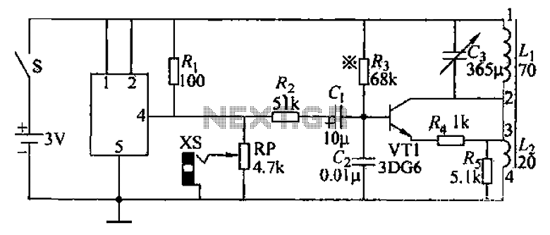
An audio frequency signal generator can output audio signals, 465 kHz spectral amplitude signals, and 52.5 Hz to 16 kHz high-frequency amplitude-modulated signals. The high-frequency oscillator's vibration frequency is determined by the components G and L. A variety of...
This audio noise filter circuit is a bandpass filter designed for the audio frequency range. It effectively filters out unwanted signals that fall outside the audio frequencies. The circuit consists of two filters: a low-pass filter and a high-pass...
Warning: include(partials/cookie-banner.php): Failed to open stream: Permission denied in /var/www/html/nextgr/view-circuit.php on line 713
Warning: include(): Failed opening 'partials/cookie-banner.php' for inclusion (include_path='.:/usr/share/php') in /var/www/html/nextgr/view-circuit.php on line 713