
Fridge Door Alarm Schematic 2nd Version

The circuit design utilizes a combination of a photoresistor and a CMOS integrated circuit to create a low-power alarm system that functions effectively within the constraints of battery-operated devices. The use of the photoresistor allows for light detection, which is essential for triggering the alarm when the refrigerator door is opened. The astable multivibrator configuration of IC1 ensures that the circuit can generate a consistent oscillation, which is crucial for the timing of the alarm signal.
The choice of components is critical for ensuring the reliability of the circuit at lower voltages. The replacement of the original 4060 CMOS IC with an alternative design allows for continued operation at reduced battery levels, addressing the issue of premature circuit failure. The compact design of the enclosure allows for easy installation within the refrigerator, ensuring that the alarm system is unobtrusive yet effective.
The output from IC1, once activated, drives IC2, which in turn controls the piezo sounder. This component is responsible for generating the audible alarm signal, providing a clear indication when the refrigerator door is left open. The intermittent nature of the alarm, with a 17-second on and off cycle, helps to conserve battery life while still providing a noticeable alert to the user.
Overall, this circuit design presents a robust solution to the limitations of previous fridge door alarm systems, ensuring functionality even under lower voltage conditions while maintaining ease of use and installation.The main purpose of this design was to obviate a small defect of the very popular Fridge Door Alarm circuit, available on this website since 1999 and built by a lot of hobbyists. Unfortunately, that circuit stops operating when the battery voltage falls below about 2. 6 2. 7 Volts. This is due to the 4060 CMos IC used. In some cases, devices mad e by some manufacturers (but not Motorola`s) fail to operate even at nominal 3V supply voltage. A simple cure to this shortcoming could be the substitution of the original IC specified with a 74HC4060 chip: this should allow circuit operation down to 2V but, unfortunately, this IC is not easy to locate. For this reason, an equivalent circuit using about the same parts counting was developed, in order to allow safe operation even when battery voltage falls down to about 1.
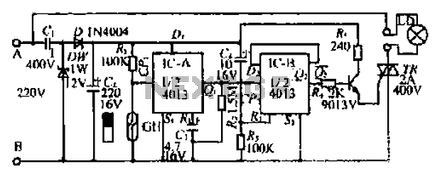
3V. The circuit, enclosed in a small box, should be placed in the fridge near the lamp (if any) or close to the opening. With the door closed, the interior of the fridge is in dark, the photo resistor R2 presents a high resistance (>200K) thus clamping IC1 by holding C1 fully charged across R1 and D1.
When a beam of light enters from the opening, or the fridge lamp lights, the photo resistor lowers its resistance (<2K) stopping C1 charging current. Therefore IC1, wired as an astable multivibrator, starts oscillating at a very low frequency and after a period of about 24 sec.
its output pin (#3) goes high, enabling IC2. This chip is also wired as an astable multivibrator, driving the Piezo sounder intermittently at about 5 times per second. The alarm is activated for about 17 sec. then stopped for the same time period and the cycle repeats until the fridge door closes. 🔗 External reference
Related Circuits

The Jammer is a very small circuit and can fit inside a small plastic box with 9V battery inside. It can be very illegal if you attach an external antenna so don't. adjust frequency by turning trimmer. It is...
Purchase a 1W white LED and utilize a mobile phone battery to create a small lamp. A lampshade can be made from a glass-like milky white plastic bottle. The LED emits light through a radiating plate, which has two...

The components include B2 (13) and B3 (14) designated for the Hall current sensor; FU9 (9) and FU10 (10) serve as fuses; an AP646 alarm signal is connected to the fuse board; terminals X24, X26, and X29 function as...

This circuit alerts users with an alarm whenever the AC mains supply fails. It also provides a backup light to assist in locating a torch or generator key in the dark. The circuit is powered by a 9V PP3/6F22...

In this circuit, the alarm activates under four different conditions: 1. When light falls on LDR1 (located at the entrance). 2. When light on LDR2 is obstructed. 3. When door switches are opened or a wire is cut. 4....

It is easy to miss the sound of a doorbell while watching TV. This circuit addresses the issue by providing a visual indication, such as a lamp or an LED. Connecting a lamp directly in parallel with the doorbell...