
full bridge inverter with mosfet ir2110

The full bridge inverter circuit design incorporates key components such as the IRF2807 MOSFETs and IR2110 driver ICs, which are crucial for efficient power conversion and switching. The IRF2807, with its high voltage and current ratings, is suitable for handling the demands of the system, particularly with a 34V input and a maximum current requirement of 10A. The IR2110 drivers are selected for their ability to drive the high-side and low-side MOSFETs effectively, providing the necessary gate drive voltage levels for switching.
The choice of a hysteresis current control method is significant, as it allows for adaptive control of the switching frequency, which can enhance performance under varying load conditions. The specified maximum frequency of 100 kHz indicates a need for careful selection of components to handle rapid switching without introducing excessive losses or thermal issues.
To achieve isolation between the microcontroller and the power circuit, the proposed use of an optocoupler is a common practice. The configuration involving the ATmega 8535 microcontroller, buffer IC, optocoupler, and IR2110 is designed to ensure that the control signals are transmitted without direct electrical connection, thus protecting the microcontroller from high voltages present in the power circuit.
Further considerations include the recommendation to use fast recovery diodes in the circuit. This modification can improve the efficiency of the inverter by reducing reverse recovery losses, which is particularly important in high-frequency applications. Adjusting resistor values may also be necessary to optimize the performance of the circuit, ensuring that the gate drive signals are appropriately tailored to the characteristics of the MOSFETs and the overall circuit dynamics.
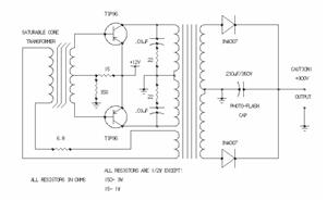
The alternative suggestion of employing an isolation transformer provides a robust method for ground isolation, which can simplify the design by removing the need for high-side driver ICs. This approach allows for the use of a gate drive transformer, which can effectively isolate the control signals while providing the necessary drive capability for the MOSFETs. The totem-pole configuration would further enhance the drive strength, ensuring reliable switching performance under varying load conditions.
Overall, the design of the full bridge inverter circuit requires careful consideration of component selection, isolation methods, and control strategies to achieve optimal performance and reliability in the intended application.For the full bridge inverter circuit i planned to use IRF2807 (75V Vds, 82A Ids) and Two IR2110 for the driver. I never use IR2110 before and failed many time when i want to make a H-Bridge for DC motor last year.
My DC input voltage is 34V (2 series solar panel), The power rating is about 100Watt so the MOSFET should able to drain about 10A max c urrent. The output of the inverter will be connected to 18V - 220V step up transformer. My controller will use hysteresis current control method so the switching frequency is not fixed and varied up to 100kHz. and i want to isolate (different ground) between my micro controller and power circuit. How can i use the optocoupler to isolate it is there any optically isolated buffer since i planned to use buffer (micro controller (ATmega 8535, 16MHz -> Buffer IC -> Optocoupler -> IR2110).
Based on the specification, is there any component that i should change read before to change the diode to the fast recovery one, and change the resistor value. If you have to isolate your ground, I would recommend you to use isolation transformer instead of optocoupler.
In this, you will no longer need to use high-side capable driver ICs, you will instead use a small gate drive transformer, buffered by the totem-poles. 🔗 External reference
Related Circuits
A car inverter, also known as a power converter or power inverter, is a device that converts 12V DC from a vehicle’s electrical system into 220V AC for general electrical use. It serves as a convenient power adapter for...
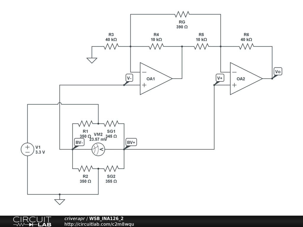
A half-bridge setup is utilized with strain gauges and an INA126 to amplify the voltage. The voltage can be read accurately when the lever is bent in one direction; however, no reading is obtained when the lever is bent...
This simple power MOSFET audio amplifier circuit utilizes a TL071C operational amplifier and two MOSFETs (IRF9530 and IRF530), capable of delivering up to 45 Watts to an 8-ohm speaker. The schematic is based on a Siliconix application and incorporates...
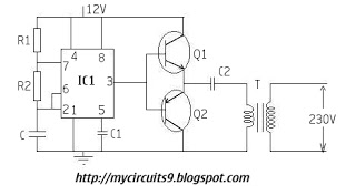
The timer IC (NE555) is configured as an astable multivibrator in this circuit. It generates an alternating non-sinusoidal output waveform as soon as a supply voltage of 12V is applied. Therefore, alternating voltage is produced from direct current (battery)....
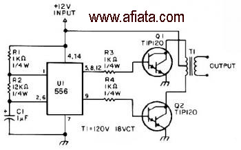
The first section of the 555 timer is configured as an astable oscillator, with R2 and C1 determining the frequency. The output is accessible at pin 5. The second section functions as a phase inverter, with its output available...
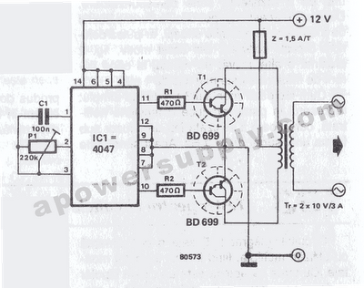
The inverter circuit features the CMOS 4047 as its primary component, converting a 12V DC voltage to a 220V AC voltage. The 4047 operates as an astable multivibrator. A symmetrical rectangular signal is generated at pins 10 and 11,...