
Full-duplex Intercom
The intercom design employs a straightforward architecture that enhances usability and minimizes feedback issues. The use of the TDA7052 audio power amplifier is particularly advantageous due to its efficiency and ability to deliver sufficient power for intercom applications. The design's focus on preventing feedback through careful phase manipulation of the microphone signals is critical in maintaining audio clarity and user comfort.
To elaborate on the circuit components, the TDA7052 IC is a low-voltage audio amplifier with built-in gain control, making it suitable for battery-powered applications. Its ability to operate within a 6V to 12V range allows for flexibility in power supply selection. The microphone amplifier Q1 plays a pivotal role in signal processing, where the phase-shifted output is essential for the feedback cancellation strategy. Capacitors C3 and C4, along with resistors R7 and R8, form a mixing network that finely tunes the balance between the in-phase and out-of-phase signals, ensuring that the loudspeaker output remains at a low level while still allowing the second unit to receive a clear signal.
The inclusion of the "Private" switch enhances the functionality of the intercom, providing users the option to mute the microphone when privacy is required. This feature is particularly useful in environments where confidentiality is necessary. The design's modularity allows for easy installation and expansion, as the two units can be placed in different locations while still maintaining a reliable connection through the screened cable.
Overall, this intercom design exemplifies an effective solution for hands-free communication, addressing common issues such as feedback while providing user-friendly features that enhance the overall experience.This design allows to operate two intercom stations leaving the operator free of using his/her hands in some other occupation, thus avoiding the usual "push-to-talk" operation mode. No complex changeover switching is required: the two units are connected together by means of a thin screened cable.
As both microphones and loudspeakers are always in operation, a special circuit is used to avoid that the loudspeaker output can be picked-up by the microphone enclosed in the same box, causing a very undesirable and loud "howl", i. e. the well known "Larsen effect". A "Private" switch allows microphone muting, if required. The circuit uses the TDA7052 audio power amplifier IC, capable of delivering about 1 Watt of output power at a supply voltage comprised in the 6 - 12V range.
The unusual feature of this design is the microphone amplifier Q1: its 180 ° phase-shifted audio output taken at the Collector and its in-phase output taken at the Emitter are mixed by the C3, C4, R7 and R8 network and R7 is trimmed until the two incoming signals almost cancel out. In this way, the loudspeaker will reproduce a very faint copy of the signals picked-up by the microphone.
At the same time, as both Collectors of the two intercom units are tied together, the 180 ° phase-shifted signal will pass to the audio amplifier of the second unit without attenuation, so it will be loudly reproduced by its loudspeaker. The same operation will occur when speaking into the microphone of the second unit: if R7 will be correctly set, almost no output will be heard from its loudspeaker but a loud and clear reproduction will be heard at the first unit output.
The circuit is shown already doubled in the diagram. The two units can be built into two separate boxes and connected by a thin screened cable having the length desired. Enclosing the power supply in the box of one unit, the other unit can be easily fed by using a two-wire screened cable, its second wire becoming the positive dc path.
To setup the circuit, rotate the volume control (P1) of the first unit near its maximum and speak into the microphone. Adjust Trimmer R7 until your voice becomes almost inaudible when reproduced by the loudspeaker of the same unit.
🔗 External reference
Related Circuits
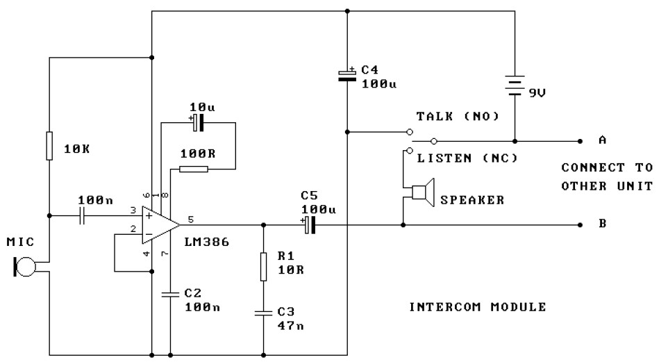
This is a two-station intercom system that operates using two wires connecting each intercom unit. Each unit is self-contained, equipped with its own battery, speaker, microphone, and amplifier circuit. An LM386 audio power amplifier is utilized, which is widely...
The circuit described can connect two telephones in parallel and function as a two-line intercom. Typically, a single telephone is connected to a telephone line. When another telephone is needed at a distance, a parallel line is utilized for...
The circuit described is a simple intercom system that utilizes a single LM386 integrated circuit, a 2N3904 transistor, and several additional components. The LM386 is a widely recognized amplifier IC commonly employed by electronics enthusiasts in audio applications. In...
This card incorporates a constant current source to activate the phone. The LM339 is utilized to detect both the presence and absence of a hand. Duplicate circuits are implemented due to the eight-phone interface. When a hand is detected...
Tro telephones can be utilized as an intercom through the implementation of this circuit. Traditional rotary phones, particularly those that are non-electronic, may be the most effective for this purpose. Additionally, this method can also power handsets alone. The circuit...
Typically, a single telephone is connected to a telephone line. If an additional telephone is needed at a distance, a parallel line is installed for connecting the second telephone. This straightforward parallel line arrangement presents issues such as loss...