
2-Line Intercom-Cum-Telephone Line Changeover Circuit
The circuit operates by utilizing a combination of switches and a buzzer to facilitate communication between the telephones while maintaining functionality with the exchange line. The use of a 3-pole, 2-way slide switch (S3) is critical as it allows for seamless operation between intercom and changeover modes. In intercom mode, the connection between telephone 1 and telephone 2 enables direct communication without interference from the exchange line, ensuring privacy during conversations. The activation of the buzzer (PZ2) serves as an auditory signal that alerts the second user to an incoming communication request.
The circuit design incorporates a voltage supply of 12V, which powers the telephones and the buzzer. The interruption of this voltage supply when switch S3 is toggled ensures that only the designated telephone (telephone 2) is active during a call on the exchange line, preventing any unwanted interruptions or ringing in the other telephones. This feature is essential for maintaining the integrity of the communication system.
Furthermore, the circuit's architecture allows for easy transition between modes, making it user-friendly. The requirement of informing the other party before switching modes adds a layer of communication etiquette, ensuring that both parties are aware of the changes being made. This thoughtful design consideration enhances the overall user experience.
In conclusion, this circuit effectively provides a solution for connecting multiple telephones while minimizing interference and maintaining privacy, making it suitable for both residential and small office environments where multiple lines of communication are necessary.The circuit presented here can be used for connecting two telephones in parallel and also as a 2-line intercom. Usually a single telephone is connected to a telephone line. If another telephone is required at some distance, a parallel line is taken for connecting the other telephone.
In this simple parallel line operation, the main problem is loss of privacy besides interference from the other phone. This problem is obviated in the circuit presented here. Under normal condition, two telephones (telephone 1 and 2) can be used as intercom while telephone 3 is connected to the lines from exchange. In changeover mode, exchange line is disconnected from telephone 3 and gets connected to telephone 2.
For operation in intercom mode, one has to just lift the handset of phone 1 and then press switch S1. As a result, buzzer PZ2 sounds. Simultaneously, the side tone is heard in the speaker of handset of phone 1. The person at phone 2 could then lift the handset and start conversation. Similar procedure is to be followed for initiation of the conversation from phone 2 using switch S2. In this mode of operation, a 3-pole, 2-way slide-switch S3 is to be used as shown in the figure. In the changeover mode of operation, switch S3 is used to changeover the telephone line for use by telephone 2.
The switch is normally in the intercom mode and telephone 3 is connected to the exchange line. Before changing over the exchange line to telephone 2, the person at telephone 1 may inform the person at telephone 2 (in the intercom mode) that he is going to changeover the line for use by him (the person at telephone 2). As soon as changeover switch S3 is flipped to the other position, 12V supply is cut off and telephones 1 and 3 do not get any voltage or ring via the ring-tone-sensing unit.
Once switch S3 is flipped over for use of exchange line by the person at telephone 2, and the same (switch S3) is not flipped back to normal position after a telephone call is over, the next telephone call via exchange lines will go to telephone 2 only and the ringtone-sensing circuit will still work. This enables the person at phone 3 to know that a call has gone through. If the handset of telephone 3 is lifted, it is found to be dead. To make telephone 3 again active, switch S3 should be changed over to its normal position. 🔗 External reference
Related Circuits

In some buildings, there is a need for effective security measures. An example of this is the door knock alarm, which is a simple design intended for basic home security. This circuit utilizes a piezoelectric sensor to detect knocking...

The circuit diagram is designed for precise control of DC motors. It converts DC voltage into a series of pulses, where the duration of each pulse... The circuit utilizes a pulse-width modulation (PWM) technique to regulate the speed and torque...
The circuit consists of a temperature sensor, electronic switches for temperature control, and a vocal language output system. During hot summer months, the central processing unit (CPU) of PCs frequently experiences overheating. The circuit, with VT1 positioned near the...
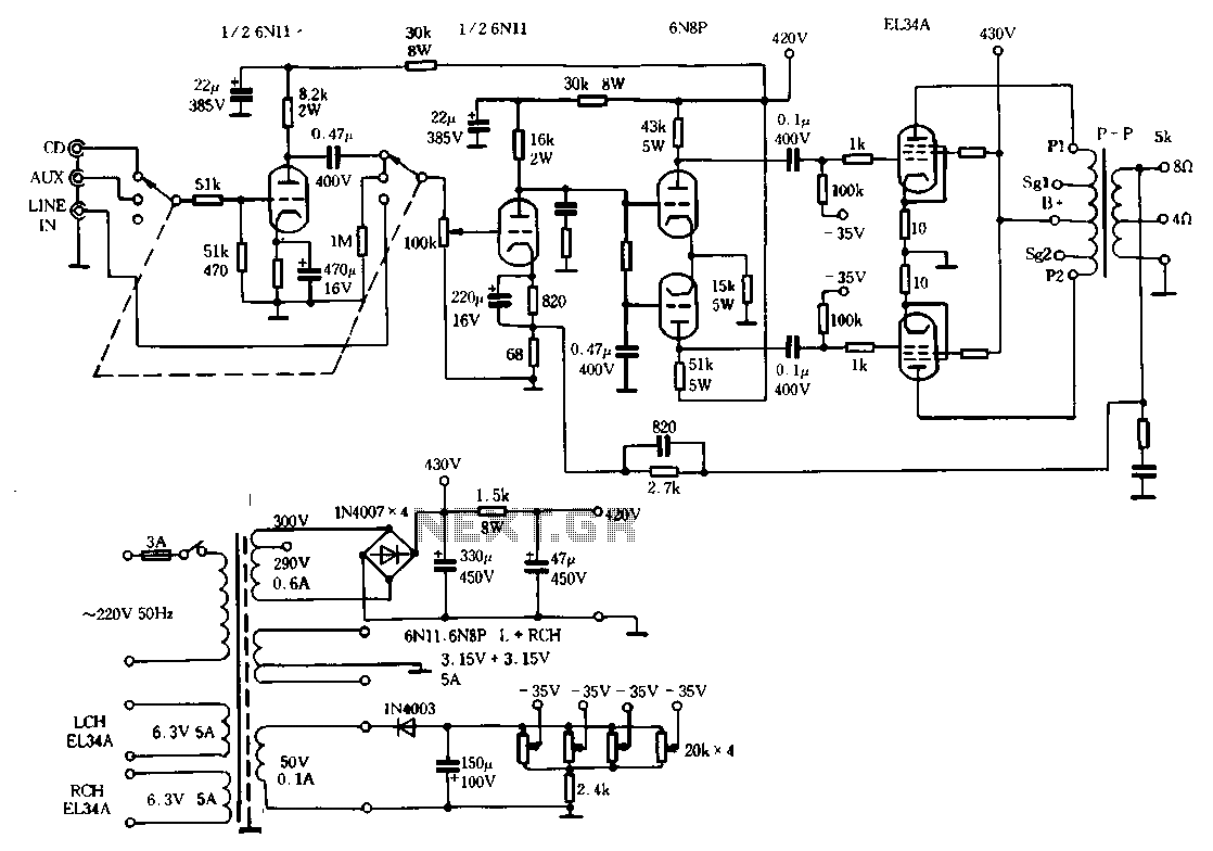
The Ml00 circuit is a typical tube circuit, functioning as a preamplifier. Its input stage utilizes a common cathode amplifier, followed by an inverter stage, culminating in a power amplifier that has been enhanced from a standard connection. This...
This circuit illustrates a Go-No/Go Tester Circuit utilizing a 555 Timer IC. Features include a more advanced unit with a precise timed testing procedure. The Go-No/Go Tester Circuit is designed to evaluate components or assemblies by providing a simple pass/fail...
Solar panels operate at optimal parameters when positioned at the ideal angle to the sun. This alignment is achieved by rotating the solar panels to track the sun's movement. A DIY solar tracker system can be constructed using an...