
Full-Wave Rectifier circuit
The full-wave rectifier circuit is essential for converting alternating current (AC) to direct current (DC) effectively. The two-diode configuration typically requires a center-tapped transformer, which splits the AC waveform into two halves. Each diode conducts during its respective half-cycle: CR1 conducts during the negative cycle, and CR2 conducts during the positive cycle. This arrangement allows the circuit to utilize both halves of the AC waveform, thereby increasing the efficiency of the conversion process.
In contrast, the four-diode bridge rectifier configuration does not necessitate a center-tapped transformer, making it a more compact and versatile solution. This configuration allows for the same full-wave rectification by arranging the diodes in a bridge layout, where current can flow through the appropriate diode pair depending on the polarity of the input AC signal.
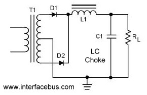
The schematic representation of the circuit provides a visual guide to the current flow, indicating how the diodes are oriented to allow current to pass during both cycles. The output voltage is smoothed by employing an LC filter, which consists of an inductor (L) and a capacitor (C). The inductor works to maintain a steady current, counteracting fluctuations that may arise due to the pulsating nature of the rectified output. Meanwhile, the capacitor acts to filter out voltage spikes and dips, ensuring that the output voltage remains as constant as possible.
The combination of these components results in a reliable DC output that can be used in various applications requiring stable voltage levels, such as power supplies for electronic devices, battery chargers, and other circuits that rely on DC power.A circuit that uses both positive and negative alternations in an alternating current to produce direct current. There are two types of Full-Wave Rectifier circuits; one that only uses two diodes but requires a center tapped transformer [shown below], and one that uses four diodes and does not require a center tapped transformer; The schematic shows the direction of current flow during each cycle of the alternating AC waveform.
The positive cycle of the AC input flows through CR2, while the negative AC cycle flows through CR1. The DC output voltage is shown for both AC cycles, as is the combination of the combined cycles. This schematic shows the same 2-diode rectifier using an LC Choke. The inductor of the filter attempts to keep the current constant while the capacitor attempts to keep the output voltage steady.
🔗 External reference
Related Circuits
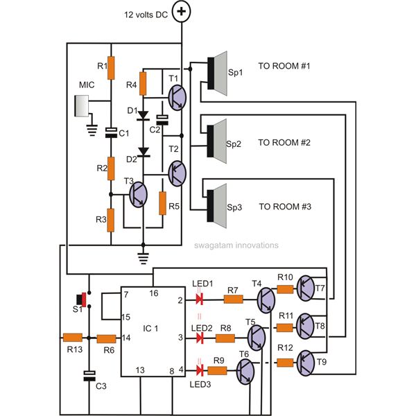
A home intercom system can be constructed using a versatile circuit design. This system allows communication across up to ten different locations or rooms discreetly. It utilizes a single changeover switch for selecting the desired location, replacing the traditional...
Given the variety of equipment in modern home entertainment systems, the ability to adjust the gain of both audio and video signals has become essential. This particular circuit has proven to be very useful when used alongside the General...
This is a variation on the astable multivibrator. Circuit was recently developed to test for N-mosfets (the power kind e.g. irf830). I don't claim circuit can test all bad mosfets or all fault mosfet conditions. If mosfet is working...

When switches SW1, SW2, or SW3 are open, the input sensitivity is optimized for high-output devices such as CD players, tuners, tape recorders, iPods, miniDisc players, and computer audio outputs. The 750 Ohm value for resistors R3, R13, and...
The mixer can accommodate any number of channels as needed by duplicating the input sections illustrated in the schematic. One instance of this mixer featured 25 inputs. The mixer circuit is designed to provide flexibility in channel configuration, allowing for...
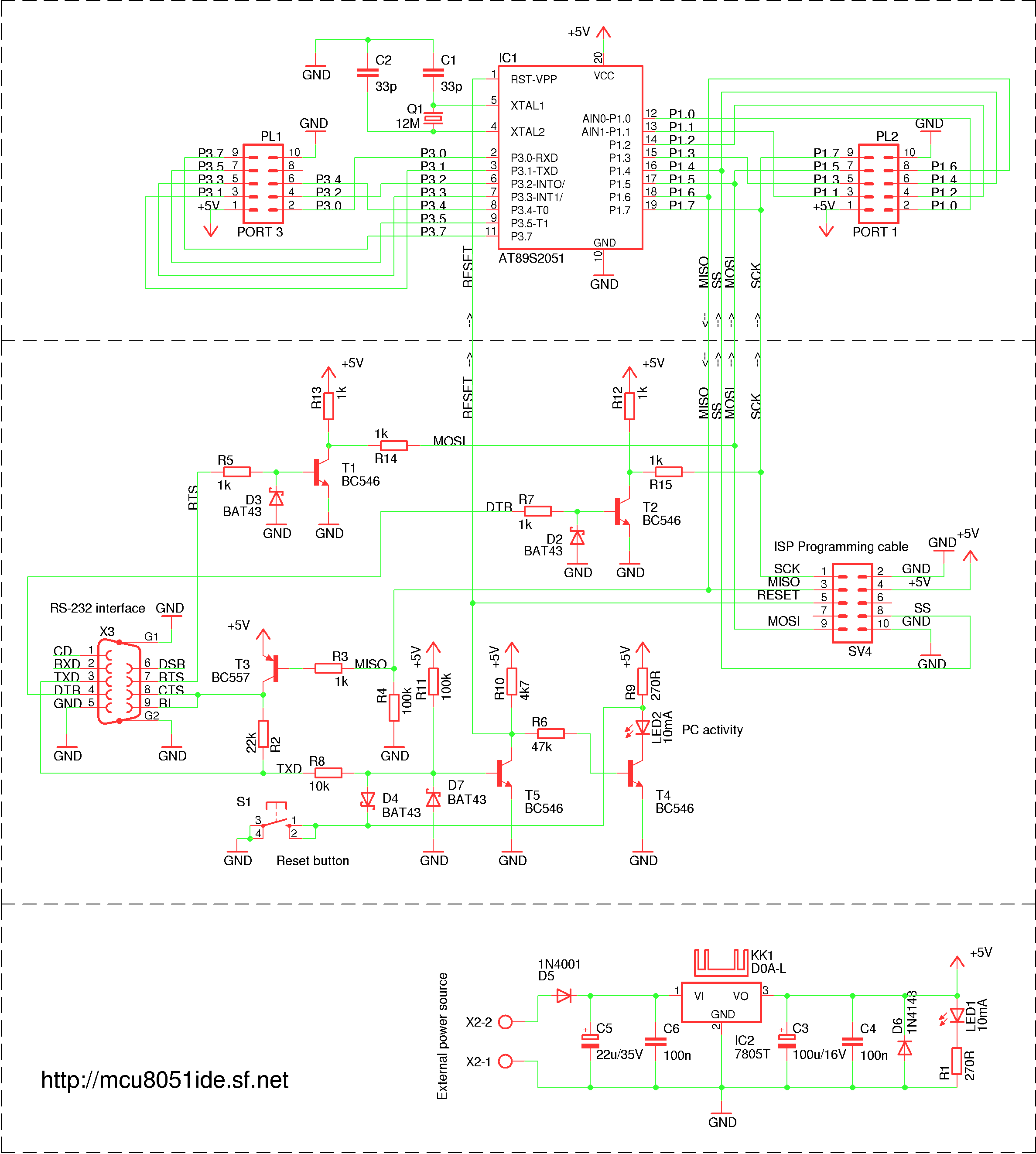
A simple RS-232 ISP programmer designed for AT89Sx devices, intended for educational purposes and hobbyist use. It has been tested with the AT89S2051 and AT89S8253 microcontrollers, utilizing a USB to serial port converter cable equipped with a PL2303 chip....