
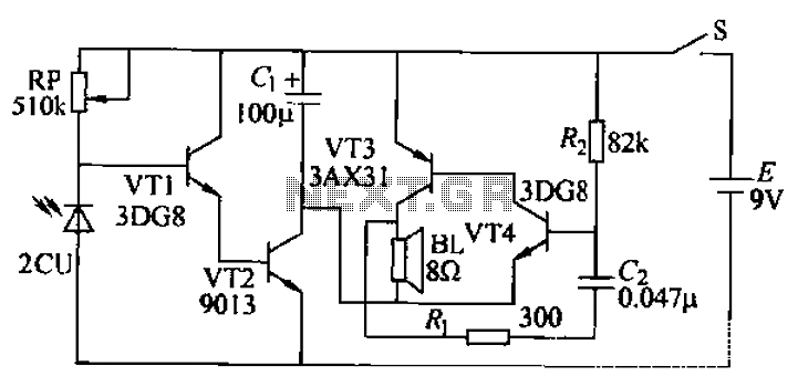
Fun and easy to build buzzer circuit
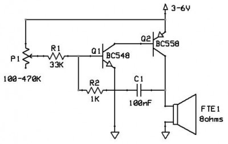
The oscillator circuit is designed to create audio signals through a feedback loop involving a transistor, which amplifies the oscillations generated by the interaction of the resistor, capacitor, and variable resistor. The variable resistor allows for fine-tuning of the frequency, enabling users to adjust the pitch of the sound emitted by the speaker. The circuit's simplicity, consisting of only seven components, makes it an excellent project for beginners in electronics.
The loudspeaker serves as the output device, converting the electrical signals from the oscillator into audible sound waves. The choice of an 8-ohm speaker is crucial, as it matches the circuit's output characteristics, ensuring efficient power transfer and optimal sound quality. The maximum power rating of 0.25 W indicates that the speaker can handle the circuit's output without distortion or damage.
Capacitor C1 plays a pivotal role in determining the frequency of oscillation. Its value, when altered, affects the charging and discharging time, thereby changing the tone produced. The resistor R1, in conjunction with the variable resistor P1, further influences the oscillation frequency, allowing for a wide range of sound variations. This flexibility in component values encourages experimentation, enabling users to explore different sound characteristics and develop a deeper understanding of oscillatory circuits.
Safety precautions should be observed during testing, particularly regarding volume levels. It is advisable to start with lower volume settings and gradually increase them to prevent hearing damage. Additionally, the circuit can be housed in a suitable enclosure to protect the components and ensure safe operation. Overall, this oscillator circuit serves as an engaging introduction to sound generation and electronic principles.This circuit is an oscillator, and is able to generate a sound wave, a tone. The tone`s frequency (if it`s a high or low sound) is controlled by the variable resistor. The sound volume of this circuit is considerable so, don`t put your ear too close to the speaker on the first run The circuit can be used as a bell, a sound warning, small alarms, simple sirens, etc (leave your application
ideas on the comments section at the bottom). When I was in high-school I made a game as a project for the Electricity course. I made that game where you have a twisted wire that runs inside a metal ring; the goal is to take the ring from one extreme of the wire to the other, without ever touching the wire with the ring. If the wire and ring touched, a bulb lamp would turn on. This was what my teacher allowed me to do, but a few hours before project delivery I built this circuit inside a cheese box and connected it in parallel with the lamp, adding a quite audible buzz to any game playing failure.
My teacher didn`t comment on my work, but he spent about 15 minutes looking inside the cheese box :). The circuit is quite simple, consisting of only 7 components, including the loud-speaker (FTE1). The speaker must have an impedance of at least 8ohm (it is usually written in the speaker itself). You can get one of these speakers easily, but also scavenge them from old small pocket radios (maybe even found on the street) or a PC speaker taken from an old PC.
The speaker you can see in the photo below was taken from a toy given with a MacDonald`s Happy Meal! It`s a nice speaker, 8 ohms and 0. 25 W maximum power, excellent for small projects as this one. The values of variable resistor P1, capacitor C1 and resistor R1 define the tone`s frequency and are not critical. You can try other values for C1, bigger or smaller than 100nF, as long as they are not polarized; a bigger capacitor like 680nF with a big R1 like 2.
2M will give you a heart beat -like sound, whereas a small value like 47nF with the original R1 value will make unbearable ear cracking sounds You can try any non-polarized capacitor that you can put your hands on, even if you don`t know its value (like capacitors taken from old radios or TVs). If you train your ears with known capacitor values you can even be able to guess an unknown capacitor value just by its sound in this circuit.
🔗 External reference
Related Circuits
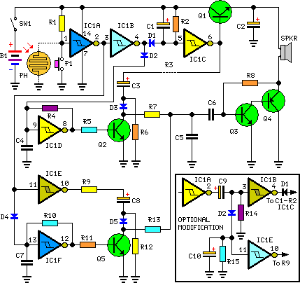
This circuit generates dual-tone bell ringing similar to most doorbell units. It can be used in various applications beyond just doorbells. Several options will be provided in the notes to accommodate different needs. The circuit, as depicted in the...
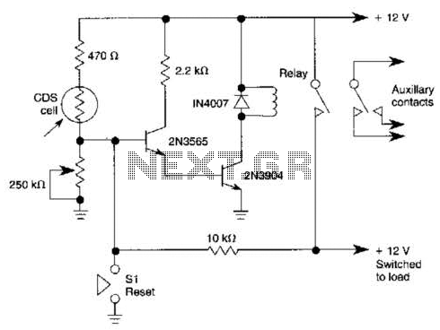
When light strikes the CDS cell, it activates the transistors, which in turn energizes the relay, causing it to latch. Pressing switch SI grounds the base of the 2N3565 transistor, thereby resetting the relay. Additionally, a 250 k potentiometer...
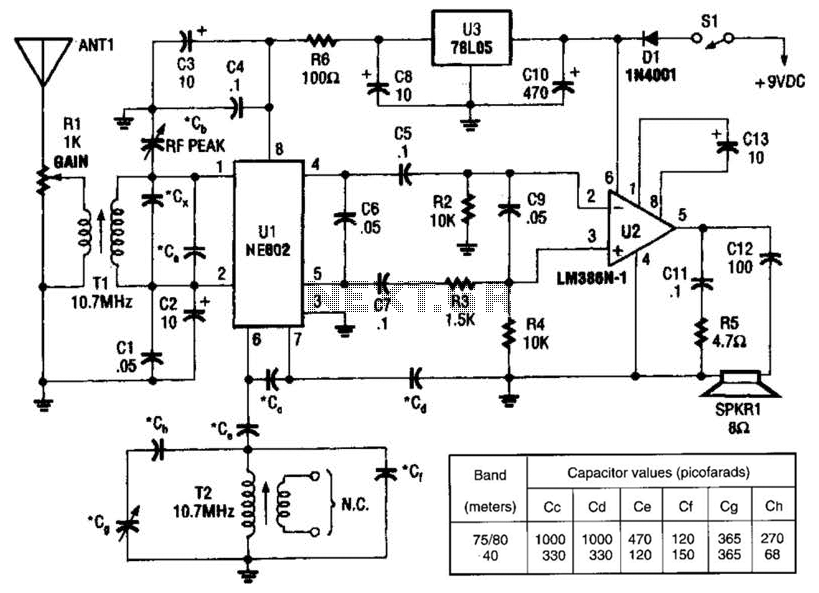
An NEC602 is utilized as a mixer with a zero intermediate frequency (IF) output, while U2 functions as an audio amplifier. This receiver is mainly designed for single sideband (SSB) and continuous wave (CW) signals. T1 and T2 are...
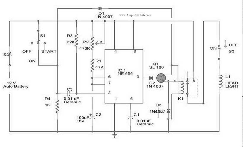
The circuit diagram for the automatic headlights turn-off circuit is presented here. This circuit can be installed in a car. The automatic headlights turn-off circuit is designed to enhance vehicle safety and convenience by ensuring that the headlights are automatically...
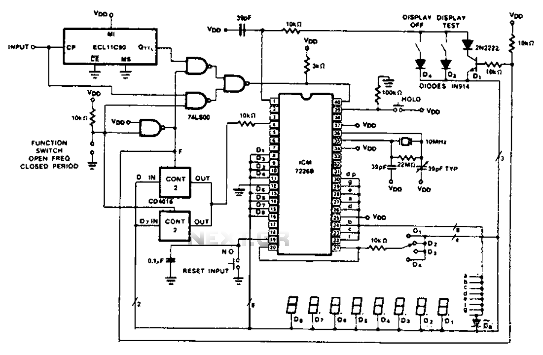
A CD4016 analog instrument is utilized as a multiplexed digital output, transferring the output function back to the input. The CD4016 operates as a digitally controlled analog transmission gate, eliminating the need for a digital output level shift. Alternatives...
Boiling water or cooking with a gas stove can sometimes lead to the fire being extinguished due to water spills, which can result in a significant gas overflow and pose a risk of poisoning. This example describes a stall...
Warning: include(partials/cookie-banner.php): Failed to open stream: Permission denied in /var/www/html/nextgr/view-circuit.php on line 713
Warning: include(): Failed opening 'partials/cookie-banner.php' for inclusion (include_path='.:/usr/share/php') in /var/www/html/nextgr/view-circuit.php on line 713