
Gas flameout alarm circuit

The stall alarm circuit is designed to enhance safety in environments where gas stoves are used. The primary function of the circuit is to monitor the presence of fire through infrared radiation detection. The photodiodes are critical components that respond to the thermal emissions from a flame. Under normal operation, when the fire is active, the infrared radiation causes the resistance of the photodiodes to decrease, effectively keeping the transistors VT1 and VT2 in a closed state. This prevents the audio oscillator from activating.
In the event of a fire extinguishment, the absence of infrared radiation leads to an increase in the photodiode’s resistance. This change triggers the opening of VT1 and VT2, which allows current to flow to the audio oscillator formed by VT3 and VT4. The oscillator generates a sound signal that is output through the connected speaker, alerting users to the hazardous condition.
The choice of components is essential for the circuit's performance. The 2CU or 2AU photodiodes are selected for their sensitivity to infrared light, while the silicon and germanium transistors are chosen for their switching capabilities and amplification properties. The use of a trimmer potentiometer allows for fine-tuning of the circuit, ensuring reliable operation under varying conditions.
Overall, this stall alarm circuit serves as a vital safety feature for gas stove operations, providing an audible warning in case of fire extinguishment, thereby reducing the risk of gas leaks and potential poisoning. Proper installation and maintenance of this circuit are crucial for ensuring its effectiveness in preventing accidents in the kitchen or other areas where gas stoves are used. Boil water or cook with gas stove, it is sometimes due to water spills extinguish the fire mission, if not found to cause a lot of gas bF overflow occurs risk of poisoning. Thi s example describes the stall alarm circuit, when the fire goes out, it will send a loud alarm. Turn off the alarm circuit is shown in Figure 13-27. Photosensitive diodes and transistors VT1, VT2 composition electronic light control switch, VT3, VT4 composed of complementary audio oscillator. When the fire burning strongly photodiode infrared radiation leaving the resistance drops, this time VT1, VF2 are closed, oscillator VT3, VT4 does not work.
When the fire goes out, infrared radiation disappeared, photodiode electrical resistance rises immediately to make VT1, VT2 quickly turned oscillator VT3, VT4 get power supply by VT2, a speaker that is made out of voice. Available 2CU photodiode or 2AU series photodiodes. VT1, VT4 an ordinary 3DG8 silicon transistor, port value of 100 or so, VT2 available 9013-type silicon transistor, the sound value is greater than 50, VT3 available 3AX31B type germanium transistors, mouth to a value greater than 30, available RP trimmer.
The remaining components such as circuit
Related Circuits

Many sites do not provide circuits for driving these transformers; they simply state that they are ineffective. However, this assertion is contested. A circuit has been developed that operates effectively, with significant effort invested in determining the resonant frequency...

The aim of this project was to develop a linear analogue amplifier designed for laboratory use. This amplifier has to realise a voltage amplification of 10x and is intended to amplify function generator signals for tests. Power supply requirements:...

An astable multivibrator is a switching circuit that alternates its output on and off for a designated time period. This device, also known as a free-running oscillator circuit, is primarily utilized to generate square waves over a specified duration....
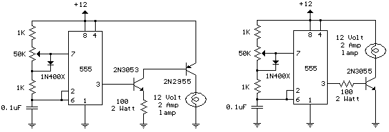
The schematic diagram illustrates a 12 Volt Car Lamp Dimmer Circuit Design utilizing a 555 Timer. This circuit can be employed to dim a standard 25-watt lamp. The 12 Volt Car Lamp Dimmer Circuit utilizes a 555 Timer in astable...

The antenna consists of approximately 20 cm of insulation made from strands, which are glued together inside a small plastic box. An RF current is processed through two diode rectifiers, and a 10k potentiometer is connected to the pin...
A NE555 integrated circuit (IC) is utilized for the design of a variable low-frequency oscillator, and a schematic is provided. The NE555 timer IC is a versatile and widely used device in various electronic applications, particularly in generating precise timing...