
Fun with LEDs
The described circuit employs several components to achieve automated lighting control in the kitchen and bathroom, enhancing convenience and safety. The use of LED strips provides energy-efficient illumination with a long lifespan. The integration of PIR sensors allows for motion detection, ensuring lights are only activated when needed, thus conserving energy. The gradual dimming feature enhances user experience by providing a soft transition to darkness, which is particularly beneficial in low-light environments. The choice of components, such as the BISS0001 IC for the PIR sensors and the IRF9530 for driving the LED strips, reflects a careful consideration of available materials while maintaining functionality. The circuit design incorporates a voltage divider to set the light threshold, ensuring that the lights activate appropriately based on ambient light conditions. The use of a simple current-limiting resistor instead of a constant current supply reduces complexity and potential thermal issues, making the circuit more reliable. Overall, this automated lighting system exemplifies a practical approach to home illumination, utilizing readily available components to create a functional and efficient solution.I have recently stumbled upon some LED strip at my local electronics shop and decided to give them a try. I bought some which I used to replace the spot lights in the kitchen. It is cold white, which is surprisingly good, especially for night time illumination (think moonlight like hue).
It works at 12V and consumes about 0. 25A per meter. After in stalling the strip, some automation proved to be necessary, and so the following circuits were built. The goal in mind was to keep things as simple as possible and use only parts I had at hand, which is why the solution might not be the best.
The hallway spotlights got new white LEDs as well and a light sensor. Tiny PIR sensors will turn on the lights in the kitchen and bathroom when someone comes in range. The sensors are rather popular modules using a BISS0001 IC; they provide a 3. 3V level for an adjustable time when motion is detected. Overall the results are great. The hallway is lit at night, the there is a small automatic light for the bathroom and the automatic kitchen light is bright enough even for day time illumination of the sink and counter. The slow turn off provides both a visually pleasing effect and a warning in case someone stood still long enough to make the light go off.
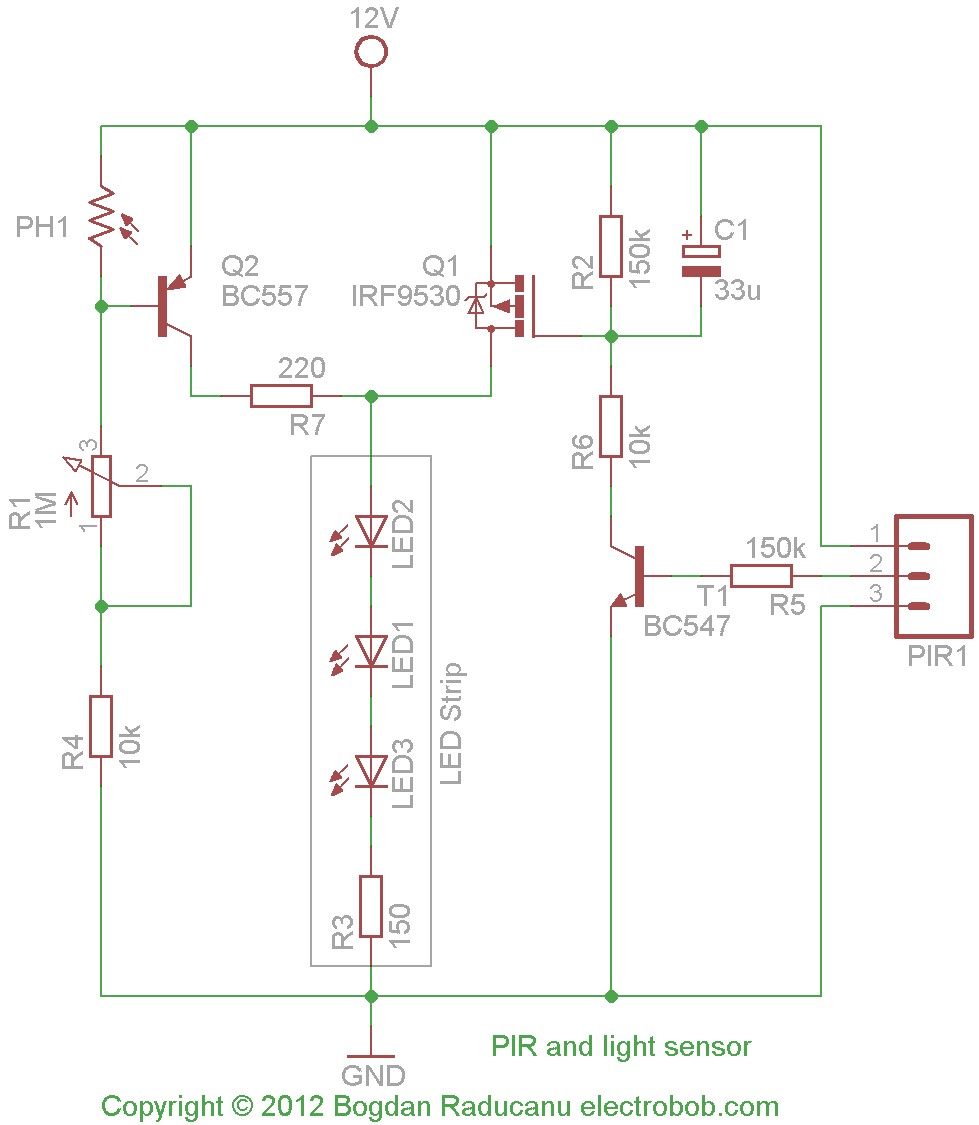
I am still looking for a simple solution to produce the same effect on turn on, but without the delay. The circuit is used to turn on the hallway lights. T2 will turn off when it is dark enough, allowing T1 to turn ON and light up the LEDs. The threshold is determined by the divider formed with a photo resistor and a potentiometer. I gave up using a constant current supply in the favor of a simple current limiting resistor because at around 100mA of current (set with R3) there is no danger of thermal runaway.
The PIR sensors themselves cannot turn on a strip of LEDs so, for the bathroom light I have used a simple transistor amplifier. The light is made up of just 20cm of light strip consuming about 50mA, but it produces enough light for a sleepy person to be able to use the bathroom without the need of the bright waking main light.
Driving the transistor through the diode insures and instant on, but once the PIR turns off, C1 will discharge through R2 slowly turning off the LEDs during a few seconds. My initial desire was to have the same effect at turn on, but the time required to charge the capacitor up to the threshold voltage will produce a few seconds of delay which in practice causes undesirable effect.
For the kitchen strip I wanted both of the functions above: a dim light when it gets dark and motion sensor turn on. The circuit is not exactly the combination of the two since I had to take into account different things.
First, the light sensor was simplified since I found out that 10mA (limited by R7) worth of current through the strip produce enough light for the night (yes, that little current makes the strip give enough light to see what it is in front of me). This means that a single transistor is enough. The light sensor turn on circuit became a little more complicated, mostly due to the parts I had available.
The transistor has to drive more current (close to 0. 5A) and support the heating produced during the slow turn off when it will dissipate more power. The only suitable transistor I had available was an IRF9530. This required another transistor to drive it. Just like the previous circuit, turn on carried as fast as possible, but the light turns off in a few seconds. R6 was initially 150K, until I discovered that this produces a delay in turn on. It may be simply shorted. The mounting conditions forced me to use an aluminum profile for first fixing the strip onto it and to split the whole thing in two pieces.
Unfortunately, Murphy caught in: Other notes: The strips were sprayed with a few layers of acrylic to ensure good insulation, just for added safety, as the power supply is insulated from the mains. 🔗 External reference
Related Circuits
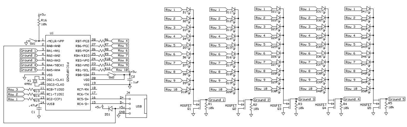
To control 40 LEDs using a single PIC 18F2455 microcontroller, the LEDs were organized into a configuration of four columns, each containing 10 rows of LEDs. Each LED in a column was connected to a separate pin on the...
This Project Multi-Pattern Running light is used to generate several designs of Running Lights. We use ten LEDs for display. The designs can be selected by using two switches UP and DOWN. The 8 bit Microcontroller is used to...
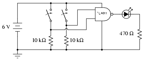
To start, connect a single NAND gate to two input switches and one LED, as illustrated. Initially, using an 8-position switch and a 10-segment LED bar graph may appear excessive, given that only two switches and one LED are...
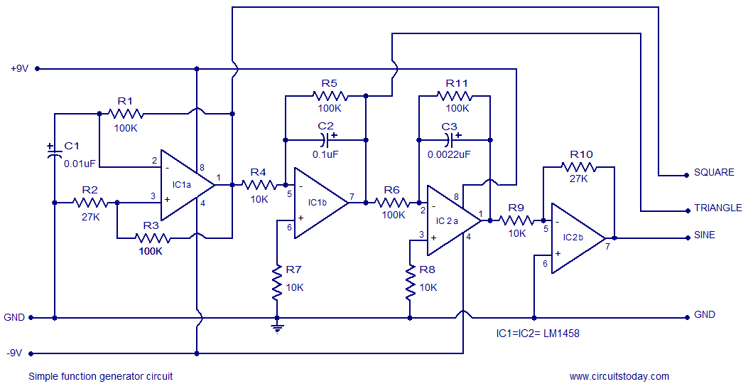
A simple function generator circuit utilizing the LM1458 is presented here. The LM1458 is a dual general-purpose operational amplifier. The two op-amps within the LM1458 share a common bias network and power supply line, yet operate independently. The function generator...

This low-cost function generator, based on the Maxim MAX038 high-frequency waveform generator, produces sine, triangle, and square waves from under 1 Hz to over 20 MHz. The function generator utilizing the Maxim MAX038 is designed to provide a versatile range...
This circuit is built around a single 8038 waveform generator integrated circuit (IC), capable of producing sine, square, or triangle waves across four switched frequency ranges from 20Hz to 200kHz. It features both high and low-level outputs, which can...