
Fundamentals of Electrical Engineering and Strain gauges
To mitigate the effects of wire resistance, careful circuit design and layout are crucial. The introduction of additional resistors in series with the strain gauge can help illustrate the impact of wire resistance on the overall measurement accuracy. The strain gauge resistance (Rgauge) is not the only factor that influences the circuit's performance; the resistance of the connecting wires must also be accounted for to ensure precise readings. This consideration is particularly important in high-precision applications, where even minor variations in resistance can lead to significant measurement errors. Proper calibration of the entire system, including the bridge circuit and any associated instrumentation, is essential for achieving reliable and accurate strain measurements. Additionally, the selection of appropriate materials for both the strain gauge and the wiring is vital, as they must maintain their properties under varying environmental conditions and mechanical stresses. Overall, the integration of strain gauges into measurement systems requires a comprehensive understanding of both the mechanical and electrical principles involved in force measurement, ensuring that the resulting data is both accurate and useful for engineering applications.If a strip of conductive metal is stretched, it will become skinnier and longer, both changes resulting in an increase of electrical resistance end-to-end. Conversely, if a strip of conductive metal is placed under compressive force (without buckling), it will broaden and shorten.
If these stresses are kept within the elastic limit of the metal strip (so that the strip does not permanently deform), the strip can be used as a measuring element for physical force, the amount of applied force inferred from measuring its resistance. Such a device is called a strain gauge. Strain gauges are frequently used in mechanical engineering research and development to measure the stresses generated by machinery.
Aircraft component testing is one area of application, tiny strain-gauge strips glued to structural members, linkages, and any other critical component of an airframe to measure stress. Most strain gauges are smaller than a postage stamp, and they look something like this: A strain gauge`s conductors are very thin: if made of round wire, about 1/1000 inch in diameter.
Alternatively, strain gauge conductors may be thin strips of metallic film deposited on a nonconducting substrate material called the carrier. The latter form of strain gauge is represented in the previous illustration. The name "bonded gauge" is given to strain gauges that are glued to a larger structure under stress (called the test specimen).
The task of bonding strain gauges to test specimens may appear to be very simple, but it is not. "Gauging" is a craft in its own right, absolutely essential for obtaining accurate, stable strain measurements. It is also possible to use an unmounted gauge wire stretched between two mechanical points to measure tension, but this technique has its limitations.
Typical strain gauge resistances range from 30 © to 3 k © (unstressed). This resistance may change only a fraction of a percent for the full force range of the gauge, given the limitations imposed by the elastic limits of the gauge material and of the test specimen. Forces great enough to induce greater resistance changes would permanently deform the test specimen and/or the gauge conductors themselves, thus ruining the gauge as a measurement device.
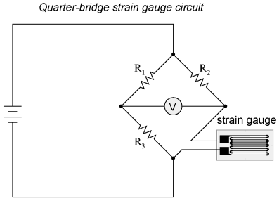
Thus, in order to use the strain gauge as a practical instrument, we must measure extremely small changes in resistance with high accuracy. Such demanding precision calls for a bridge measurement circuit. Unlike the Wheatstone bridge shown in the last chapter using a null-balance detector and a human operator to maintain a state of balance, a strain gauge bridge circuit indicates measured strain by the degree of imbalance, and uses a precision voltmeter in the center of the bridge to provide an accurate measurement of that imbalance: Typically, the rheostat arm of the bridge (R2 in the diagram) is set at a value equal to the strain gauge resistance with no force applied.
The two ratio arms of the bridge (R1 and R3) are set equal to each other. Thus, with no force applied to the strain gauge, the bridge will be symmetrically balanced and the voltmeter will indicate zero volts, representing zero force on the strain gauge. As the strain gauge is either compressed or tensed, its resistance will decrease or increase, respectively, thus unbalancing the bridge and producing an indication at the voltmeter.
This arrangement, with a single element of the bridge changing resistance in response to the measured variable (mechanical force), is known as a quarter-bridge circuit. As the distance between the strain gauge and the three other resistances in the bridge circuit may be substantial, wire resistance has a significant impact on the operation of the circuit.
To illustrate the effects of wire resistance, I`ll show the same schematic diagram, but add two resistor symbols in series with the strain gauge to represent the wires: The strain gauge`s resistance (Rgauge) is not the o 🔗 External reference
Related Circuits
The following circuit illustrates the wiring diagram and electrical circuit troubleshooting for the 1997 Chevrolet Blazer. Features include a 4.3-liter Vortec V-6 engine, an AM-FM stereo radio with CD player, rear-wheel drive managed by a four-speed automatic transmission, air...
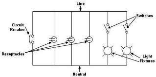
Each component of the circuit is represented in a simple block form with corresponding labels for identification, using no special symbols or language. The interconnections between these components are depicted by solid lines. The block diagrams can be read...
The following presents an electrical schematic for a 1993 VW Passat. Features include vehicle content and electrical wiring schematic. Components consist of console switches, electric windows, ABS control unit, ABS hydraulic unit, engine control module, automatic control unit, fuse/relay...
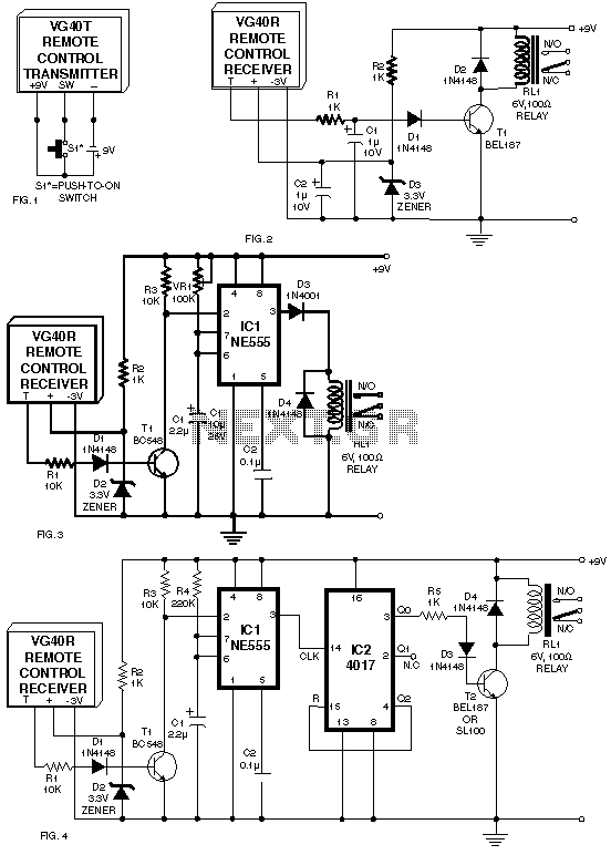
A circuit for a remote control unit utilizes radio frequency signals to operate various electrical appliances. This remote control unit features four channels, which can be expanded to twelve. Unlike typical remote control circuits that rely on infrared light...
This circuit below shows an electrical circuit applicable for the Audi A4 Quattro 2004 model year. Component: Transmission, Anti-lock Brakes Circuit. The electrical circuit for the Audi A4 Quattro 2004 model year encompasses critical components such as the transmission system...
DMRC's uniqueness lies in how it has managed soft issues related to the general public affected by it. To alleviate traffic congestion and chaos around construction sites on main roads, DMRC deployed special personnel to assist Delhi Police. Cars...