
Wiring Diagram and Electrical Circuit Troubleshooting Of 1997 Chevrolet Blazer
The wiring diagram for the 1997 Chevrolet Blazer serves as a crucial reference for diagnosing and troubleshooting electrical issues within the vehicle's systems. The schematic provides a visual representation of the electrical connections and components, facilitating the identification of faults within the wiring harnesses, connectors, and electronic modules.
Key components depicted in the diagram include the battery, alternator, starter motor, and various fuses that protect the electrical circuits. The diagram also outlines the connections for the engine control module (ECM), which manages engine operations and communicates with other electronic systems, such as the transmission control module (TCM) for the four-speed automatic gearbox.
Furthermore, the schematic illustrates the wiring for the power accessories, including the power windows, door locks, and mirrors, which are typically controlled by switches located on the driver's door panel. The air conditioning system is also represented, highlighting the connections between the compressor, condenser, and the climate control module.
The anti-lock braking system (ABS) is another critical feature represented in the wiring diagram. It includes sensors that monitor wheel speed, ensuring optimal braking performance and safety. The dual airbags are connected through a dedicated circuit to the airbag control module, which is responsible for deploying the airbags in the event of a collision.
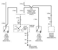
This comprehensive wiring diagram not only aids in troubleshooting electrical problems but also provides a valuable resource for modifications and repairs, ensuring that technicians can maintain the functionality and safety of the 1997 Chevrolet Blazer.The following circuit shows about Wiring Diagram and Electrical Circuit Troubleshooting Of 1997 Chevrolet Blazer. Features: powered by a 4. 3-liter Vortec V-6 engine, AM-FM stereo radio with CD, rear wheels moved through a four-speed automatic gearbox, air conditioner, 4, 400 rpm/250 lb-ft Power windows, power door locks, power mirrors, cruise contr
ol, dual air bags, anti-lock braking, producing 190 hp. [ freepdfmanual. com ] 🔗 External reference
Related Circuits
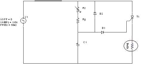
The diagram illustrates an R-C-Diode circuit that provides full half-cycle control (180 electrical degrees). During the positive half-cycle of the SCR anode voltage, the capacitor charges to the trigger point of the SCR, a process governed by the RC...
AN79 Linear Technology AN79 modifies methods presented in AN74, allowing for the verification of 30 nanosecond amplifier settling times with 0.1% resolution. The sampling-based technique used is detailed, and results are presented. Appendices cover oscilloscope overdrive issues, the construction...
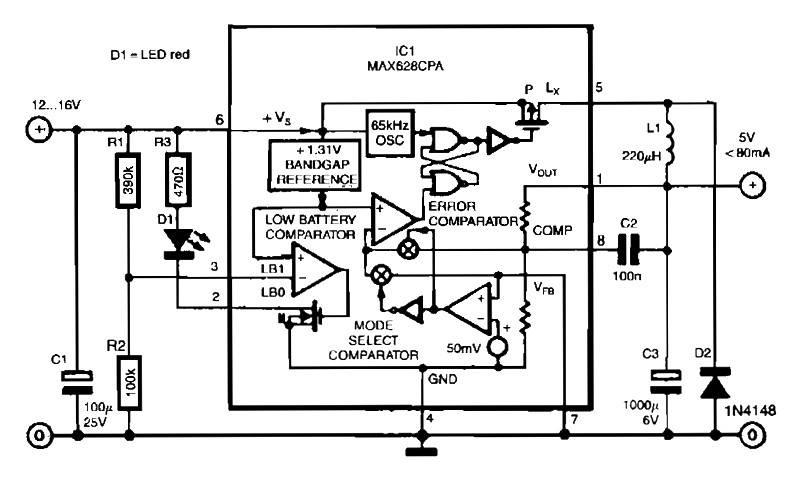
The circuit utilizes the MAX638CPA 5V CMOS Step Down Adjustable Switching Regulator IC, which converts an input voltage of 12 to 16 VDC into a stable 5VDC output. It requires only nine additional external components to complete the circuit....

When the preset is set to its maximum, the LED flashes at a rate of approximately once every half second. This rate can be increased by raising the capacitor value from 10µF to a higher value. For instance, if...
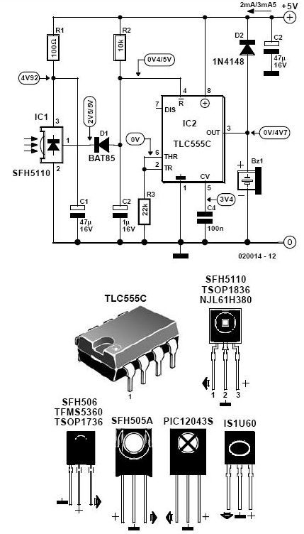
This infrared alarm barrier is designed to detect individuals passing through doorways, corridors, and small gates. The transmitter emits a beam of infrared light that remains invisible to the human eye. When a person interrupts the light beam, the...
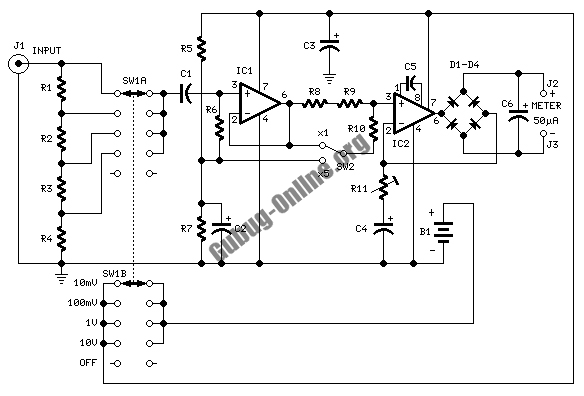
This design circuit is used to activate circuitry and an analog meter for sensitive DC current measurements. A subsequent inquiry raised the possibility of measuring AC microamperes, which inspired the idea for this circuit. The circuit is designed to facilitate...
Warning: include(partials/cookie-banner.php): Failed to open stream: Permission denied in /var/www/html/nextgr/view-circuit.php on line 713
Warning: include(): Failed opening 'partials/cookie-banner.php' for inclusion (include_path='.:/usr/share/php') in /var/www/html/nextgr/view-circuit.php on line 713