
remote control for electrical
The circuit design emphasizes versatility, allowing for the control of multiple devices from a distance. The use of DTMF tones, which are robust against noise and interference, enhances the reliability of the control signals. The integration of a zener diode voltage regulator ensures stable operation of the DTMF generator IC, while the selection of a 3.58 MHz crystal provides precise timing for frequency generation. The configuration of the FM transmitter and receiver facilitates a significant range of operation, making it suitable for use in larger areas without the constraints of line-of-sight that infrared systems impose. The toggle flip-flop arrangement allows for efficient control of appliances, ensuring that they can be turned on or off as needed, providing a practical solution for remote operation of household devices. Overall, the design is characterized by its simplicity and effectiveness, making it an innovative approach in the realm of remote control technology.A circuit of a remote control unit which makes use of the radio frequency signals to control various electrical appliances. This remote control unit has 4 channels which can be easily extended to 12. This circuit differs from similar circuits in view of its simplicity and a totally different concept of generating the control signals.
Usual ly remote control circuits make use of infrared light to transmit control signals. Their use is thus limited to a very confined area and line-of-sight. However, this circuit makes use of radio frequency to transmit the control signals and hence it can be used for control from almost anywhere in the house. Here we make use of DTMF (dual-tone multi frequency) signals (used in telephones to dial the digits) as the control codes.
The DTMF tones are used for frequency modulation of the carrier. At the receiver unit, these frequency modulated signals are intercepted to obtain DTMF tones at the speaker terminals. This DTMF signal is connected to a DTMF-to-BCD converter whose BCD output is used to switch-on and switch-off various electrical appliances (4 in this case).
The remote control transmitter consists of DTMF generator and an FM transmitter circuit. For generating the DTMF frequencies, a dedicated IC UM91214B (which is used as a dialler IC in telephone instruments) is used here. This IC requires 3 volts for its operation. This is provided by a simple zener diode voltage regulator which converts 9 volts into 3 volts for use by this IC.
For its time base, it requires a quartz crystal of 3. 58 MHz which is easily available from electronic component shops. Pins 1 and 2 are used as chip select and DTMF mode select pins respectively. When the row and column pins (12 and 15) are shorted to each other, DTMF tones corresponding to digit 1 are output from its pin 7. Similarly, pins 13, 16 and 17 are additionally required to dial digits 2, 4 and 8. Rest of the pins of this IC may be left as they are. The output of IC1 is given to the input of this transmitter circuit which effectively frequency modulates the carrier and transmits it in the air.
The carrier frequency is determined by coil L1 and trimmer capacitor VC1 (which may be adjusted for around 100MHz operation). An antenna of 10 to 15 cms (4 to 6 inches) length will be sufficient to provide adequate range. The antenna is also necessary because the transmitter unit has to be housed in a metallic cabinet to protect the frequency drift caused due to stray EM fields.
Four key switches (DPST push-to-on spring loaded) are required to transmit the desired DTMF tones. The switches when pressed generate the specific tone pairs as well as provide power to the transmitter circuit simultaneously. This way when the transmitter unit is not in use it consumes no power at all and the battery lasts much longer.
The receiver unit consists of an FM receiver (these days simple and inexpensive FM kits are readily available in the market which work exceptionally well), a DTMF-to-BCD converter and a flip-flop toggling latch section. The frequency modulated DTMF signals are received by the FM receiver and the output (DTMF tones) are fed to the dedicated IC KT3170 which is a DTMF-to-BCD converter.
This IC when fed with the DTMF tones gives corresponding BCD output; for example, when digit 1 is pressed, the output is 0001 and when digit 4 is pressed the output is 0100. This IC also requires a 3. 58MHz crystal for its operation. The tone input is connected to its pin 2 and the BCD outputs are taken from pins 11 to 14 respectively.
These outputs are fed to 4 individual D` flip-flop latches which have been converted into toggle flip-flops built around two CD4013B ICs. Whenever a digit is pressed, the receiver decodes it and gives a clock pulse which is used to toggle the corresponding flip-flop to the alternate state.
The flip-flop output is used to drive a relay which in turn can latch or unlatch any elec 🔗 External reference
Related Circuits
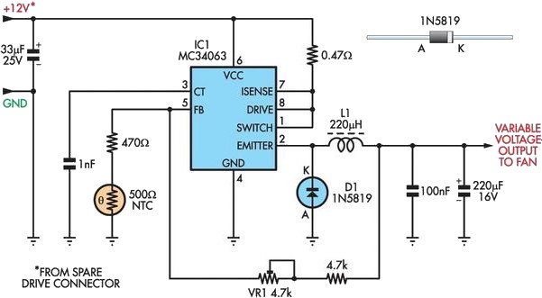
A partial solution to reducing noise from PCs can be achieved by lowering the speed of internal cooling fans. Low-cost fan speed controllers are available, but they often utilize inefficient, heat-generating linear regulators and lack a temperature feedback mechanism....
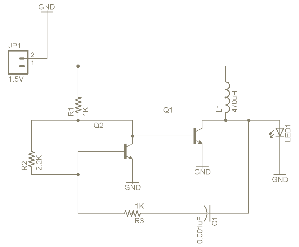
The Joule Thief is a straightforward and uncomplicated device, yet its functionality is remarkable. It can utilize a battery that is otherwise deemed unusable in any other electronic device, and it is very easy to construct on a breadboard...
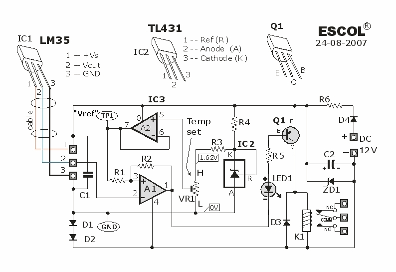
This temperature-controlled relay circuit is a simple yet highly accurate thermal control circuit that can be used in applications where automatic temperature regulation is required. The temperature-controlled relay circuit operates by monitoring the ambient temperature using a temperature sensor, such...
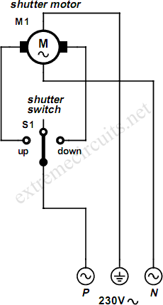
An electrically operated rolling shutter typically features a standard control panel equipped with a three-position switch that allows for up, down, and stop functions. The electrically operated rolling shutter system is designed to provide convenient control over the opening...
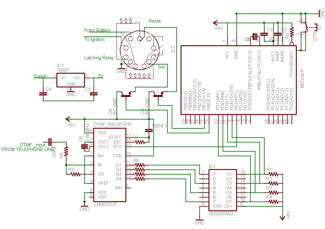
This document outlines the process of interfacing a microcontroller with a phone line. The tones generated when dialing numbers on a phone can be utilized to remotely control various devices. It provides guidance on incorporating Dual-Tone Multi-Frequency (DTMF) tones...
This circuit is beneficial for connecting a computer to homemade robotics. It is straightforward to construct and operate, capable of controlling two DC motors of varying current and voltage ratings, contingent on the specifications of the relays used. Additionally,...