
Coffee Thermometer Circuit
The coffee temperature monitoring circuit is a practical application of electronic components, combining basic elements to create a user-friendly device. The voltage regulator ensures that the circuit operates within a stable voltage range, protecting sensitive components from fluctuations. The temperature-to-voltage converter (IC2) is critical for transforming the thermal measurements into a corresponding voltage output, enabling easy processing by the comparator.
The comparator (IC3) serves as the decision-making component of the circuit. It compares the voltage from IC2 against a preset reference voltage, which is adjusted via the potentiometer (P1). When the temperature exceeds the set threshold, the comparator output transitions from low to high, triggering a change in the state of the transistors. This mechanism not only controls the LEDs but also serves as an indicator of the coffee's temperature status.
The use of two LEDs provides a clear visual indication of the coffee's temperature: the red LED signifies that the coffee is too hot, while the green LED indicates that it is at an optimal drinking temperature. This dual LED system enhances user experience by providing immediate feedback.
The inclusion of two PCB layouts allows for flexibility in design and implementation, catering to different preferences or space constraints. The circuit can be assembled in a compact form, making it suitable for personal use or as a gift for coffee enthusiasts. Overall, this coffee thermometer circuit exemplifies how simple electronic components can be integrated to solve everyday problems effectively.The circuit featured here is very useful to save you from burning your tongue. The coffee thermometer is composed of a voltage regulator, a temperature to voltage converter, a comparator and two LEDs. Roughly described, the circuit works this way: if the coffee temperature is not hot enough, the IC output is logical 0 and T1 does not conduct current.
Transistor T2 at this time conducts and the red LED lights up. If the temperature is hot enough, the green LED lights up. IC2 measures the temperature and converts it into a voltage value. Because of this, IC2 must be dipped into the coffee. IC2 can also be installed inside an empty pen wich can serve as a probe. The output of IC2 increases in proportion to the temperature by 10 mV per degree. Therefore, if you feel that by 800C the taste of the coffee is at its best, you must set the reference temperature at the minus input of the IC3 to 800 mV through P1. When the voltage level at the plus input of IC3 reaches 800 mV, the comparator output swings to logic 1 and T1 conduct currents.
At this time T2 turns off and the red LED is off. Otherwise, the green LED lights up showing that the coffee tastes good. There are two PCB layout for this coffee thermometer circuit. Choose any of the two. 🔗 External reference
Related Circuits
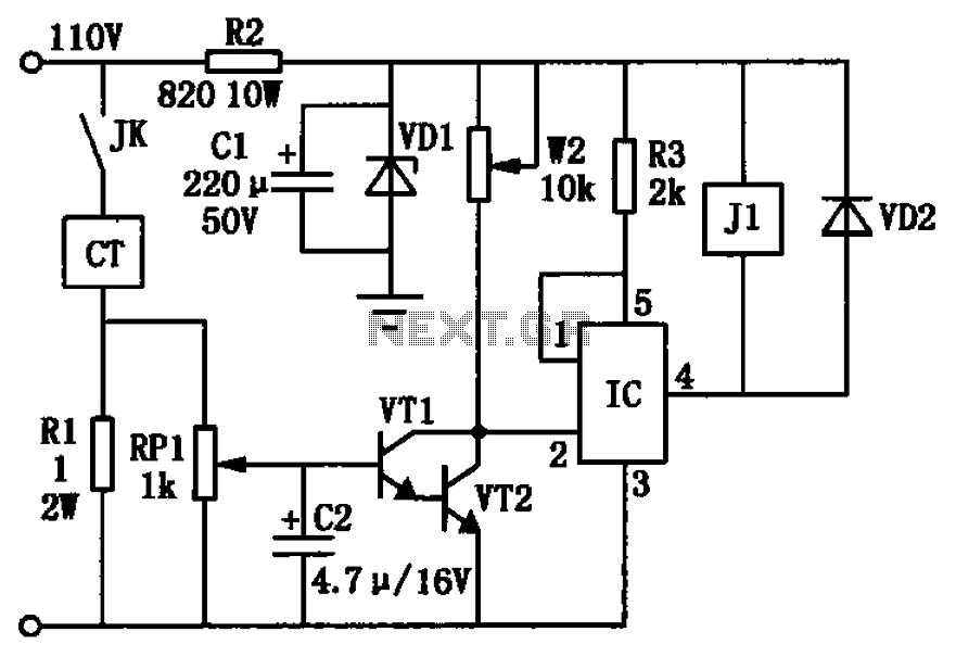
The circuit depicted in the figure utilizes a +24V power supply derived from a 110V power source through an electromagnetic chuck. When the electromagnetic chuck circuit is activated, the contact JK closes, enabling the operation of the magnetic chuck....
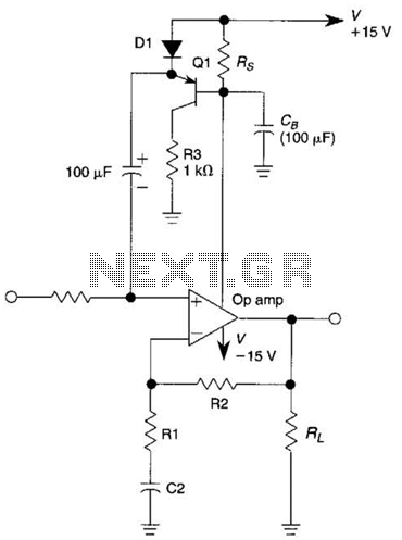
This circuit is an Automatic Gain Control (AGC) system designed for audio-frequency signals. AGC systems typically consist of three main components: an amplifier, a rectifier, and a controlled impedance. In this particular circuit, the functions of both the amplifier...
Most of the power supply failure indicator circuits need a separate power supply for themselves. But the alarm circuit presented here needs no additional supply source. It employs an electrolytic capacitor to store adequate charge, to feed power to...
A sawtooth wave generator circuit using a 555 IC is presented in the article below. The frequency equation is provided with the supply voltage Vcc. The sawtooth wave generator circuit utilizing a 555 timer integrated circuit (IC) is a fundamental...
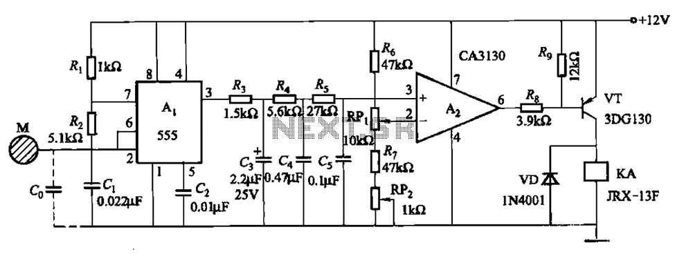
The circuit utilizes a 555 IC in conjunction with capacitors C1, C2, and a metal plate (tablet) M to create a distributed capacitance Co and resistor R1 connected to ground. Resistor R2 forms a self-excited multivibrator, while resistors R3...
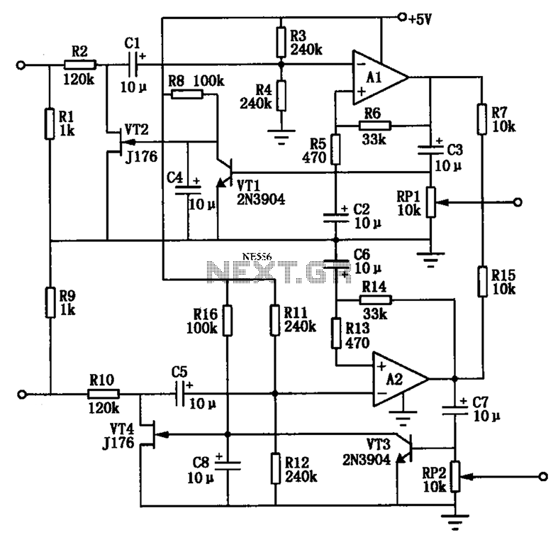
The Audio Automatic Gain Control (AGC) circuit monitors the output signal level of an audio preamplifier. When the input signal increases, the AGC circuit automatically reduces the amplifier's gain. Conversely, when the input signal decreases, the AGC circuit increases...