
Relay Selector Pushbutton circuit and explanation
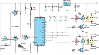
Gate IC1a is configured as a relaxation oscillator operating at approximately 20 kHz. The pulses generated by this oscillator are fed into IC1b, where they are gated with a control signal from IC1c. The output from IC1b is inverted by IC1d and sent to the clock input (CP0) of IC2. Initially, when the reset switch (S1) is pressed, it sets a logic high at the O0 output (pin 3) of IC2 and logic lows at all other outputs (O1-O9). Consequently, the relay driver transistors (Q1-Q4) are not activated, and no relays are energized, leaving all load devices (such as speakers) unselected.
When one of the selector switches (S2-S5, etc.) is pressed, for instance, pressing S5 connects the O4 output (pin 10) of IC2 to the input (pin 9) of IC1c, pulling it low. This action raises the output (pin 10) of IC1c, which in turn pulls the input of IC1b (pin 5) high, allowing clock pulses to pass to the decade counter IC2. The CD4017B counter increments until a high signal appears at its O4 output. This high signal is routed through S5 to pin 9 of NAND gate IC1c, causing its output (pin 10) to go low. This low signal also appears on pin 5 of IC1b, inhibiting further clock pulses from reaching its output (pin 4), thus stopping the counter. As a result, the counter runs briefly enough to elevate the output connected to the pressed switch.
This sequence occurs regardless of which selector switch is activated, allowing the circuit to function as an electronic interlock system. Each relay driver circuit utilizes a 2N7000 FET switch, with its gate controlled by one output of IC2 through a 100-ohm resistor. The relay coil connects from the drain to the +12V supply rail, with a reverse diode spike suppressor placed across each coil. For visual feedback of the selected output, an optional indicator LED and series resistor can be connected across each relay coil, as illustrated in the schematic. For selecting pairs of stereo speakers, relays such as the Jaycar SY-4052 are recommended, as they operate at 12V and have DPDT contacts rated for 5A. Although four selector switches are depicted in the circuit, only two relay drivers are shown due to space limitations. For a four-way selector configuration, identical relay drivers would be connected to the O2 and O3 outputs of IC2.This circuit was designed for use in a hifi showroom, where a choice of speakers could be connected to a stereo amplifier for comparative purposes. It could be used for other similar applications where just one of an array of devices needs to be selected at any one time.
A bank of mechanically interlocked DPDT pushbutton switches is the simplest w ay to perform this kind of selection but these switches aren`t readily available nowadays and are quite expensive. This simple circuit performs exactly the same job. It can be configured with any number of outputs between two and nine, simply by adding pushbutton switches and relay driver circuits to the currently unused outputs of IC2 (O5-O9).
Gate IC1a is connected as a relax-ation oscillator which runs at about 20kHz. Pulses from the oscillator are fed to IC1b, where they are gated with a control signal from IC1c. The result is inverted by IC1d and fed into the clock input (CP0) of IC2. Initially, we assume that the reset switch (S1) has been pressed, which forces a logic high at the O0 output (pin 3) of IC2 and logic lows at all other outputs (O1-O9). As the relay driver transistors (Q1-Q4) are switched by these outputs, none of the relays will be energised after a reset and none of the load devices (speakers, etc) will be selected.
Now consider what happens if you press one of the selector switches (S2-S5, etc). For example, pressing S5 connects the O4 output (pin 10) of IC2 to the input (pin 9) of IC1c, pulling it low. This causes the output (pin 10) to go high, which in turn pulls the input of IC1b (pin 5) high and allows clock pulses to pass through to decade counter IC2.
The 4017B counts up until a high level appears at its O4 output. This high signal is fed via S5 to pin 9 of NAND gate IC1c, which causes its output (pin 10) to go low. This low signal also appears on pin 5 of IC1b, which is then inhibited from passing further clock pulses on its other input (pin 6) through to its output (pin 4), thus halting the counter.
So, the counter runs just long enough to make the output connected to the switch that is pressed go high. This sequence repeats regardless of which selector switch you press, so the circuit functions as an electronic interlock system.
Each relay driver circuit is a 2N7000 FET switch with its gate driven from one output of IC2 via a 100W resistor. The relay coil is connected from the drain to the +12V supply rail, with a reverse diode spike suppressor across each coil.
If you want visual indication of the selected output, an optional indicator LED and series resistor can be connected across each relay coil, as shown. For selecting pairs of stereo speakers, we`d suggest the use of relays like the Jaycar SY-4052. These operate from 12V and have DPDT contacts rated for 5A. Note that although four selector switches are shown in the circuit, only two relay drivers are shown because of limited space.
For a 4-way selector, identical relay drivers would be driven from the O2 and O3 outputs of IC2. 🔗 External reference
Related Circuits
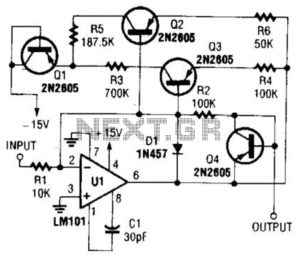
This operational amplifier circuit utilizes resistor and transistor feedback elements to function as a nonlinear amplifier. The resistors R4 and R6 can be adjusted to modify the breakpoints as needed. This operational amplifier circuit is designed to operate within the...

A hydrophone is a device similar to a microphone, designed specifically for use in underwater environments. When utilized to capture sound in air, its effectiveness diminishes. A hydrophone operates by converting sound waves into electrical signals, making it an essential...
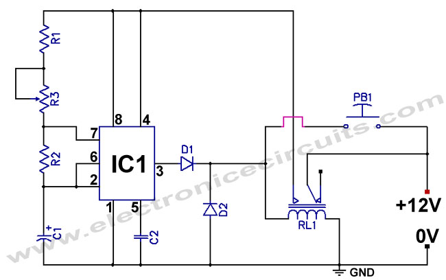
The standard 555 timer circuit consumes power from the battery even when the start push-button (PB1) is not pressed, due to a potential divider created by three 5kΩ resistors within the integrated circuit (IC). This power consumption, referred to...

This design circuit is for a tone/frequency detector (decoder) that can detect the presence of a signal with a specific tone. The output of the circuit will be active if the signal matches the tone of an internal oscillator....
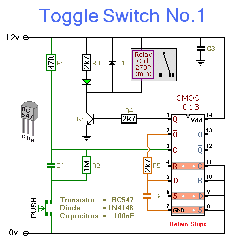
This simple circuit will energize and de-energize a relay with the push of a button. Pressing the button once will energize the relay, while pressing it a second time will de-energize the relay. The accompanying circuit provides a solid...
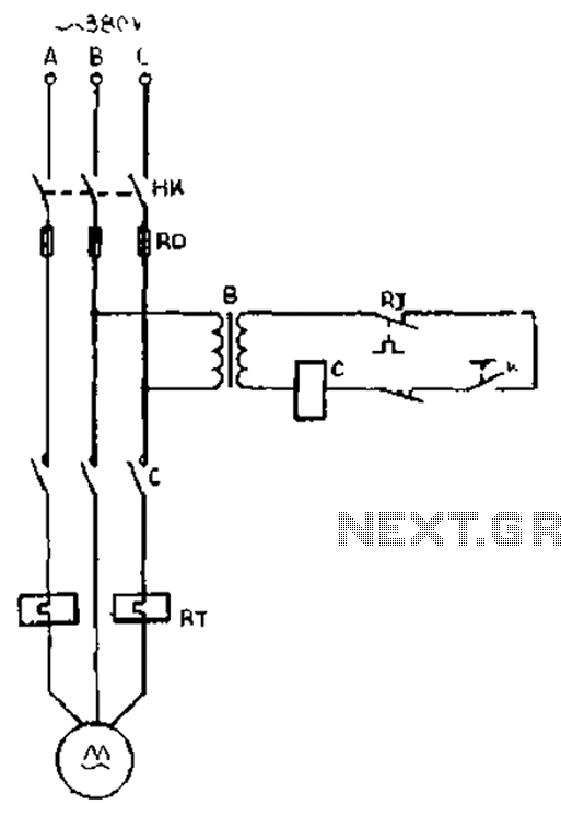
The gear lathe is unloaded from the stop line as depicted in the figure. When the turning clutch is in the stop position, the limit switch XWK is disengaged, which immediately powers the AC contactor coil C to stop...