
Game Show Indicator Lights (Whos First) circuit

The described circuit operates as a sequential button press detector, designed to illuminate a specific light based on the initial button activation in a game setting. The fundamental operation involves a combination of logic gates or a microcontroller that monitors multiple input buttons. Each button is connected to a distinct input pin, allowing the circuit to identify which button was pressed first.
In a typical configuration, the circuit may utilize a series of resistors and capacitors to debounce the button inputs, ensuring that only a single press is registered despite any mechanical bouncing that may occur. The logic circuitry can include an AND gate or a priority encoder that determines the first button pressed among the active inputs.
When the first button is pressed, the corresponding output pin is activated, which in turn energizes a relay or a transistor that controls the power to the light. The circuit can be designed to provide visual feedback through an LED indicator next to each button, illuminating only the active button to enhance user experience.
To extend the circuit for additional buttons and lamps, additional input pins can be added to the microcontroller or more logic gates can be included in the design. The scalability of the circuit ensures adaptability to various game formats, allowing for a larger number of participants while maintaining the same operational principles.
This circuit can be implemented on a printed circuit board (PCB) for durability and reliability, with careful consideration given to the layout to minimize interference and ensure consistent performance. Proper power supply regulation must also be accounted for to ensure that the circuit operates efficiently under varying load conditions.The circuit turns on a light corresponding to the first of several buttons pressed in a "Who`s First" game. Three stages are shown but the circuit can be extended to include any number of buttons and lamps.. 🔗 External reference
Related Circuits
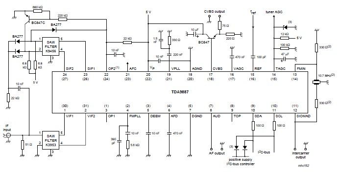
The integrated circuit (IC) is a multistandard vision and sound intermediate frequency (IF) phase-locked loop (PLL) demodulator that operates without the need for alignment. It supports multiple television standards, including PAL, SECAM, and NTSC, and is capable of handling...
LED brightness control circuit: A simple circuit can be used to control the brightness level of an LED display. The LED brightness control circuit is designed to adjust the illumination level of an LED display according to user preferences or...
The most challenging aspect of the build was to find or design a circuit capable of handling the load while remaining within budget. This circuit achieves both objectives. It adjusts the power output using a potentiometer (variable resistor) R1,...

This is a circuit design for a PWM speed control circuit for DC motor rotation. The circuit features two functions: Forward-Reverse operation and Regenerative Braking. The control is achieved using a MOSFET. The circuit allows for the control of...
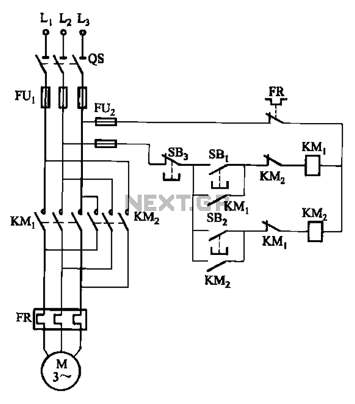
The circuit depicted in Figure 3-22 includes KMi and SBi as forward contacts and forward buttons, KMz and SB2 as reverse contactors and reverse buttons, with SB3 designated as the stop button. The circuit in question is likely part of...
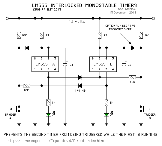
This circuit is straightforward. The initial 555 timer prevents the second timer from being activated while the first is operational. Drive the circuit with a simple 12-volt power supply. The circuit utilizes two 555 timer integrated circuits (ICs) configured in...
Warning: include(partials/cookie-banner.php): Failed to open stream: Permission denied in /var/www/html/nextgr/view-circuit.php on line 713
Warning: include(): Failed opening 'partials/cookie-banner.php' for inclusion (include_path='.:/usr/share/php') in /var/www/html/nextgr/view-circuit.php on line 713