
LM555 interlocked monostable timer circuit

The circuit utilizes two 555 timer integrated circuits (ICs) configured in a monostable arrangement. The first 555 timer serves as the primary control element, which, when triggered, generates a pulse that maintains its output high for a predetermined duration. This output is connected to the trigger input of the second 555 timer.
When the first timer is in operation, its output remains high, effectively preventing the second timer from being triggered. The timing duration for the first timer is determined by an external resistor and capacitor. The values of these components can be calculated using the formula: T = 1.1 * R1 * C1, where T is the time in seconds, R1 is the resistance in ohms, and C1 is the capacitance in farads.
The second 555 timer is designed to activate only after the first timer has completed its timing cycle. This ensures that the two timers do not interfere with each other’s operation. The output of the second timer can be used to drive additional circuitry, such as LEDs or relays, depending on the application requirements.
Powering the circuit with a 12-volt supply is ideal, as it falls within the operating range of the 555 timer ICs, which typically accept voltages from 4.5 volts to 15 volts. Proper bypass capacitors should be placed close to the power pins of each timer to ensure stable operation and minimize voltage fluctuations.
Overall, this circuit design is effective for applications requiring sequential timing operations, where the coordination of two timing events is necessary without overlap.This circuit is simple. The first 555 timer prevents the second timer from being triggered while the first is running.
Drive the circuit with a simple 12 volt power supply.
🔗 External referenceRelated Circuits
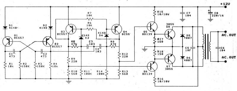
This circuit is a 100W DC inverter based on a transistored multivibrator and serves as a transistor signal amplifier. The inverter converts a 12V DC input voltage to approximately 220V AC. It is recommended to use a 12V car...
This sound-activated switch allows for sound control, which can be beneficial not only for robotic applications but also for home automation. The sound-activated switch operates by detecting specific sound frequencies or patterns, enabling the user to control various devices or...
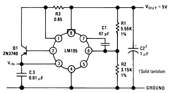
A single diffused, wide base transistor, such as the 2N3740, is recommended due to its reduced tendency to cause oscillation issues compared to double diffused, planar devices. Additionally, it exhibits greater reliability under overload conditions, and low-cost options are...
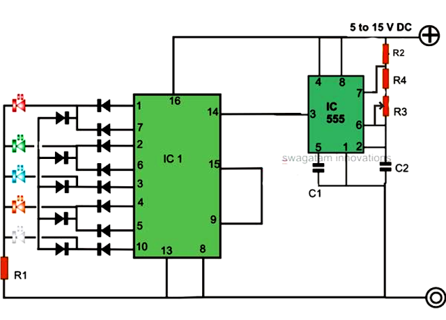
An LED light chaser circuit is an electronic configuration designed to illuminate a group of LEDs in a predetermined sequence. A commonly used integrated circuit (IC) for creating this type of LED sequencer circuit is the 4017. This IC...
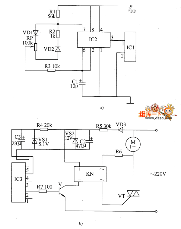
The electronic motor speed controller circuit includes a wireless remote control transmitter circuit and a wireless remote control receiver circuit, as illustrated in the accompanying chart. The wireless remote control transmitter circuit comprises a micro-power wireless remote control transmitter...
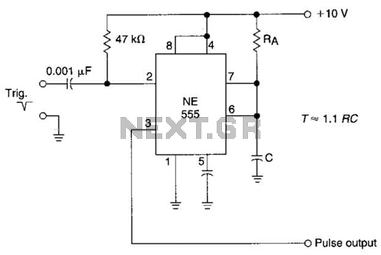
The time constant of RAXC determines the period of the monostable multivibrator. A negative pulse at pin 2 of the 555 starts the cycle. The monostable multivibrator is a circuit configuration that produces a single output pulse in response...