
Three-phase motor overcurrent protection circuit
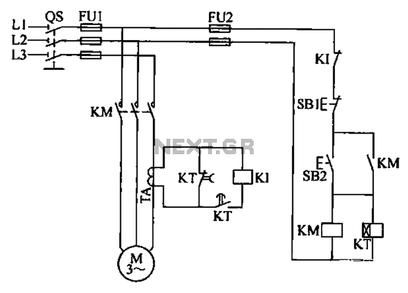
The three-phase electric motor overcurrent protection circuit is designed to safeguard the motor against excessive current conditions that could lead to overheating and failure. The circuit employs a transformer for current sensing, which is crucial for real-time monitoring of the current flowing through each phase of the motor. The overcurrent relay (K1) is calibrated to a specific threshold; if the current exceeds this threshold, K1 activates, opening its normally closed contacts. This action interrupts the power supply to the contactor (KM), effectively disconnecting the motor from the power source and preventing potential damage.
To manage the high inrush current that occurs during motor startup, a time relay is integrated into the circuit. This relay temporarily shorts the current transformer, allowing the motor to start without triggering the overcurrent protection mechanism. This design consideration is essential, as the initial current can be significantly higher than the motor's normal operating current. Once the motor reaches its operational state and the current stabilizes, the time delay relay (KT) resets, enabling K1 to resume monitoring the current levels.
The circuit's design emphasizes reliability and responsiveness, ensuring that the motor is protected without hindering its performance during startup. By incorporating both the current sensing transformer and the time delay relay, the circuit effectively balances protection and operational efficiency, making it suitable for various industrial applications where three-phase motors are utilized. Proper implementation of this protection circuit can significantly extend the lifespan of electric motors and reduce maintenance costs associated with overcurrent-related failures.A three-phase electric motor is over- current protection circuit. How it works: This example circuit uses a transformer to sense the current, three-phase motor currents exceedi ng normal operating current time. Overcurrent relay Kl pull current reaches the set value of the suction, the normally closed contacts disconnect, KM loss of power release, the main circuit power loss t thereby protecting the electric motor, to disconnect when the over-current power supply. When the motor starting current is large, with a time relay normally closed contact to the current transformer shorting avoid motor starting current flows Kl and malfunction.
Motor starting to be completed after the current is reduced to normal, by the delay time relay KT move for the normally closed contacts disconnect, normally open contact closure, the KI access current transformer circuits.
Related Circuits
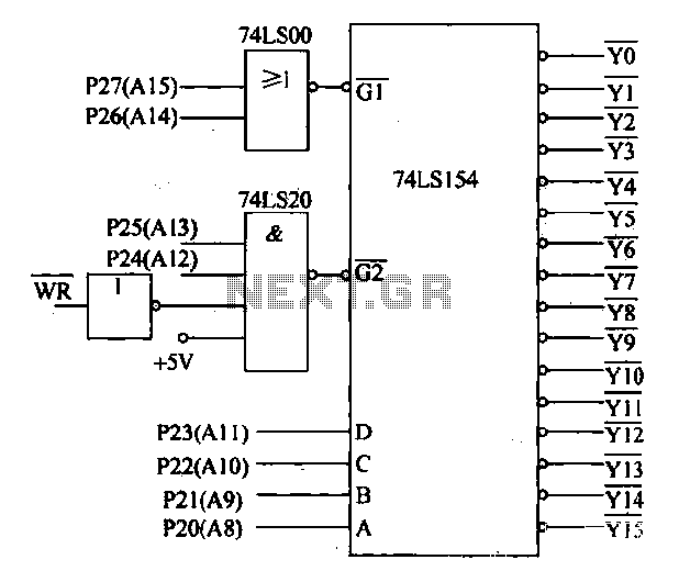
Decoding circuit: To ensure proper functionality of various interfaces, the system must assign IP addresses to all ports. Based on the number of system interfaces, it utilizes the 74LS154 decoder, which can translate up to 16 addresses. The interface...
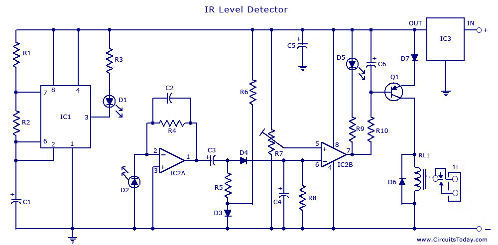
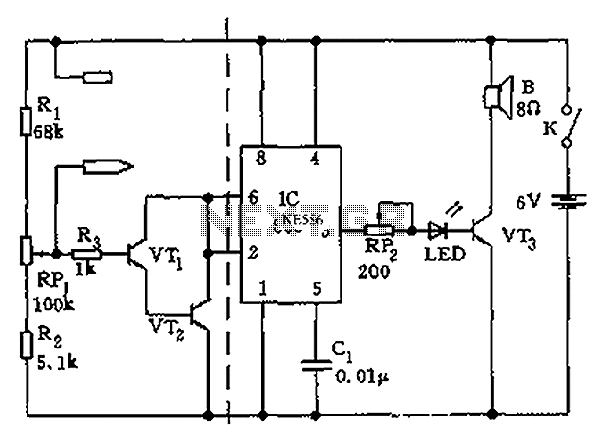
The circuit illustrates the use of a 555 Timer IC in an infrared (IR) detector configuration. It features a duty cycle of 0.8 milliseconds, a frequency of 120 Hz, and a peak current of 300 mA. The 555 Timer IC...
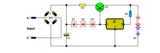
Unlike many units, this battery charger continuously charges at maximum current, tapering off only near full battery voltage. In this unit, the full load. This battery charger is designed to operate with a continuous charging mechanism, maintaining the maximum current...
The apparatus consists of a cavers point detection circuit and a triggering display circuit. The cavers instrument functions as a test probe, which, when held in one hand, can detect acupuncture points by touching the skin with another probe....
The task involved testing the capacitive properties of food by connecting various edibles to an Arduino. This project, known as BeetBox, was developed by Scott Garner, a student at NYU-ITP, who designed an innovative musical instrument that uses beets...
When the switch is pressed, capacitor C3 charges through resistor R4 with a time constant of 0.47 seconds. Upon releasing the switch, C3 discharges more slowly through resistors R7 and R3, with a time constant of approximately 5 seconds....
Warning: include(partials/cookie-banner.php): Failed to open stream: Permission denied in /var/www/html/nextgr/view-circuit.php on line 713
Warning: include(): Failed opening 'partials/cookie-banner.php' for inclusion (include_path='.:/usr/share/php') in /var/www/html/nextgr/view-circuit.php on line 713