
Gate automatic lamp circuit
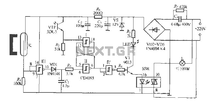
The automatic lighting circuit described operates based on the interaction between various components, primarily utilizing integrated circuits for efficient operation. The CD4093 NAND gate IC serves as the core logic device, interfacing with sensors that detect the state of doors and windows. When the magnetic field from a magnet is present, the circuit remains in a closed state, allowing current to flow through the system. This condition is maintained until the door is opened, at which point the magnetic reed relay disconnects, triggering a change in the circuit's output.
The light detection mechanism is achieved through a combination of a phototransistor and a resistor. During nighttime conditions, when ambient light levels are low, the phototransistor becomes non-conductive, leading to a low output signal. Conversely, during daylight, the phototransistor conducts, resulting in a high output signal. This differentiation between day and night is crucial for the operation of the lighting system, ensuring that lights are only activated when necessary.
The RS flip-flop configuration within the circuit serves to manage the state of the output based on the input signals received from the sensors. The truth table of the RS flip-flop indicates that the output will only transition to an active state when the door is opened (input S = 1) during nighttime conditions (input R = 0). Consequently, when the output is activated, it energizes a solid-state relay (SSR), which in turn powers the lighting element. The incorporation of a light-emitting diode (LED) provides a visual indication of the system's operational status.
A delay circuit is also integrated into the design, allowing for a predetermined duration of illumination after the door is opened. This feature is particularly beneficial in scenarios where immediate closure of the door may not occur, as it provides sufficient time for individuals to enter or exit the space. The delay is achieved through a CMOS circuit that utilizes a capacitor to extend the time before the light is turned off.
The power supply section of the circuit is designed to be efficient, utilizing a rectifier and voltage regulator to ensure stable operation without generating excessive heat. This design consideration enhances the longevity and reliability of the circuit. Components such as tantalum electrolytic capacitors are recommended for their low leakage current, which contributes to the overall efficiency of the system.
Overall, this automatic lighting circuit exemplifies a practical application of digital logic and sensor integration, providing a reliable solution for automated lighting control based on environmental conditions and user interaction.- The use of a number of integrated circuits rather gated automatic lighting circuit device formed, which consists of door and window components of the sensor, CD4093 digital integrated circuits with state relay and power supply circuit. Usually closed when the room f J. K by the magnetic field of the magnet, the electrical connection is closed, the inverter f Chuan I input high level, after inverting input rP, is low; when the deduction liter door, away from the T magnet reed relays, K jump contacts Ji door input is low, the output is high, namely: the door shut - o; door Ji-1, phototransistor WlP and R, composed of light twist circuit at night without light, VTP off, the output for the "O"; when Bai Tianbai light, Vir conduction, the output is "1." RS © NAND gate I and composed of typical fire triggers, J '] control signal and the control signals, respectively , as S (set to "l") end and R (set to "()") side of the input signal. From the RS flip-flop truth table (see Table 7 1) shows that only when R = O (ie the night, no light), S a 1 (door is opened), whose output Q that is only for the first feet " ..
" After t inverter inverting the first feet high output power + to make a diode VT conduction, solid state relays SSR opened, F lamp is lit, the light emitting diode while I, ED also lit indicates. And when R = L (ie n days, there is light). Or when so (door closed) is called, all so that the output Ql, through gates t anti After phase so V1I off, SSR off Ge, F spider will not be illuminated.
VD1, (, I and R; cyanosis to extend Trent lU Road, elbow 'i "signal delay of about 10 s so that the door is opened. When people enter (a) Li Yi Ge I, when the door not be closed, electricity spider E , but to delay 40s then off.
the delay circuit full advantage of the CMOS circuit high input Frl + / Lt larger than 10Mn), heard this training using smaller capacitors will machi obtain a relatively longer delay time: 1 as the book machine DC voltage mountain f buck, VD2 ~ VDa rectifier, vs regulator after obtaining the entire power supply section without heating element [U electrode consumption province, can pass lU among pregnant published work, the same year the electricity suddenly energized blood will not exceed ikWh "] circuit I -IV using Schmitt NAND gate 4 blocks of digital integrated circuits CI) 4003.SSR use IC, type solid state relays TA (, OIS, the maximum drive capability IA.C, suddenly find using C, 1 {B400V polypropylene capacitors , a claim .. electrolytic capacitor leakage current as small as possible for the best use tantalum electrolytic door sensor suppliers to seek common ground dagger cases, no special requirements other components.
Related Circuits

The CXA1600M and CXA1600P are 8-pin single-chip bipolar integrated circuits (ICs) designed for AM radios. These ICs encompass all necessary functions from the front-end to the power amplifier, eliminating the need for external filters, which makes the attachment of...
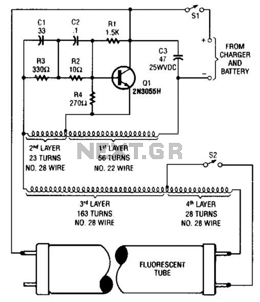
A 2N3055 oscillator (Q1) drives a homemade transformer, wound on a Vk ferrite rod. S2 is used as a filament switch and can be eliminated if desired. A 20-W fluorescent tube is recommended. The supply voltage is 12 V. The...
In this circuit, one, two or three neon indicator bulbs can be made to flash in sequence at rates determined by the R and C values. In the single stage circuit, using one lamp, the capacitor charges through the...
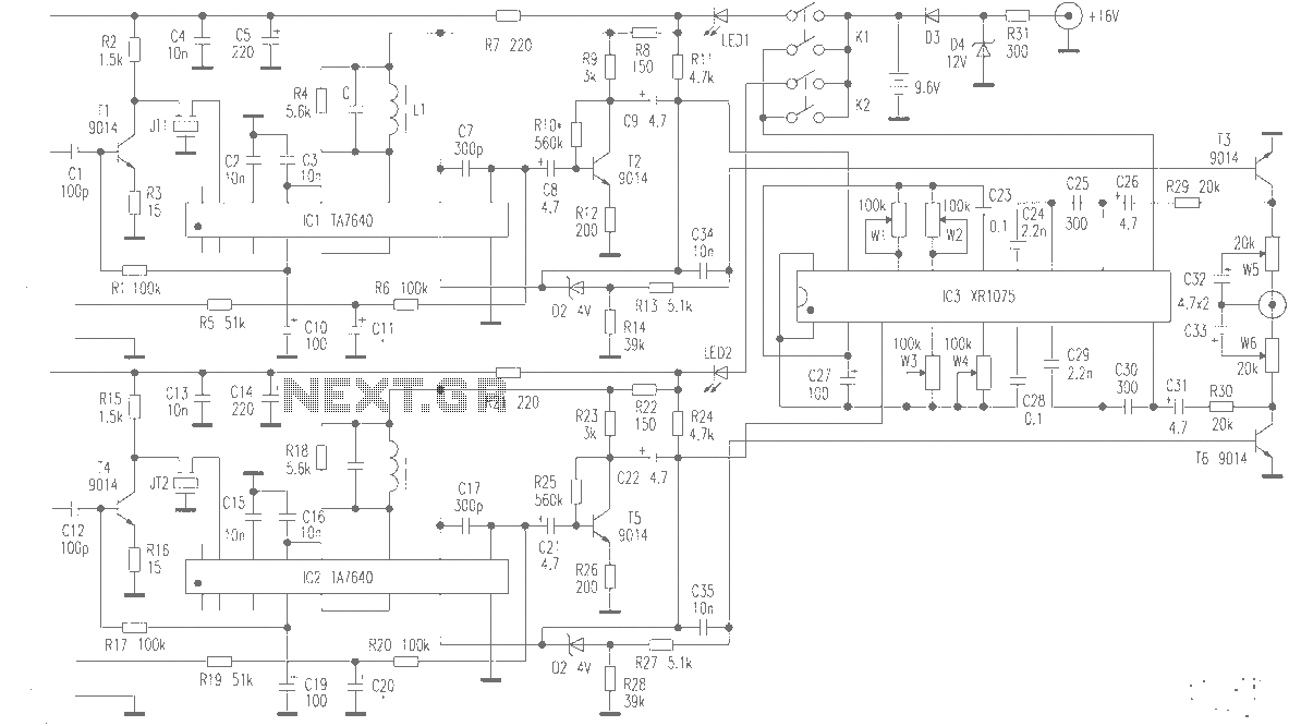
The production of high-quality wireless microphones is a common aspiration among enthusiasts, but achieving a high-performance receiver is challenging. This project explores the use of salvaged FM radio cassette players to enhance an XR1075 audio processor, leading to the...

The ICL7665S Super CMOS Micropower Over/Under Voltage Detector features two low-power, individually programmable voltage detectors integrated on a single CMOS chip. It typically requires 3 µA for operation and is designed for battery-operated systems and instruments that need high...

This 555 timer circuit toggles a relay when a button is pressed. Pins 2 and 6, which are the threshold and trigger inputs, are maintained at half the supply voltage by two 10K resistors. When the output is high,...
Warning: include(partials/cookie-banner.php): Failed to open stream: Permission denied in /var/www/html/nextgr/view-circuit.php on line 713
Warning: include(): Failed opening 'partials/cookie-banner.php' for inclusion (include_path='.:/usr/share/php') in /var/www/html/nextgr/view-circuit.php on line 713