
Neon Lamp Flashing Schematic
The described circuit is a simple neon lamp flasher, which utilizes the properties of neon gas to create a visually appealing flashing effect. The operation relies on a charging and discharging cycle facilitated by a resistor-capacitor (RC) network. When the circuit is powered, the capacitor begins to charge through the resistor. The time it takes for the capacitor to charge to the ionization voltage of the neon bulb (approximately 70 volts) is determined by the values of the resistor (R) and the capacitor (C).
Once the ionization voltage is reached, the neon bulb ignites, allowing the stored charge in the capacitor to discharge rapidly through the bulb, producing a flash of light. This discharge continues until the voltage drops below the sustaining voltage (approximately 45 volts), at which point the bulb extinguishes. The capacitor then begins to charge again, repeating the cycle.
The frequency of the flashing can be adjusted by changing the values of R and C. A smaller resistance or capacitance will result in a quicker charge time, thus increasing the flashing frequency, while larger values will decrease the frequency. It is essential to use non-polarized capacitors rated for at least 100 volts to ensure safety and reliability, as the circuit can reach high voltages during operation.
For circuits utilizing multiple stages (more than three bulbs), it is critical that the bulbs are matched in terms of their turn-on voltages to ensure uniform flashing. This matching helps maintain consistent timing and brightness across all bulbs in the sequence. The circuit can be expanded by adding additional RC networks for each subsequent bulb, thus creating a visually dynamic display.In this circuit, one, two or three neon indicator bulbs can be made to flash in sequence at rates determined by the R and C values. In the single stage circuit, using one lamp, the capacitor charges through the resistor until the ionization potential of the neon is reached (about 70 volts) and then discharges quickly through the lamp until the voltage falls below what is needed to sustain the lamp which is approximately 45 volts.
The cycle then repeats at a rate of about 3 Hz for values shown. Smaller R or C values increase frequency, larger values decrease frequency. All capacitors should be the non-polarized variety with a 100 volt or more rating. For more than 3 stages, the lamps may need to be matched for similar turn-on voltages. 🔗 External reference
Related Circuits
Circuit CREATOR Electronics CAE System provides the most complete and high performance solution for electronics design using personal computers. More: Includes PCB DESIGN -layout editor and Schematic Capture software tool, full Schematic Design and Capture, Circuit Simulation, full interactive...

This schematic represents a simple fluorescent lamp driver circuit utilizing two transistors. The circuit employs capacitive ballasting to drive an 8 W standard fluorescent tube efficiently. The two transistors (2SC 1983) and their associated components create an oscillator operating...
This circuit is designed to serve as a reliable substitute for thermally-activated switches used in Christmas tree lamp-flashing applications. The configuration comprising Q1, Q2, and associated resistors activates the SCR. Timing is managed by R1, R2, and C1. To...
Schematics for guitar effects utilizing vacuum tubes and solid-state electronics include the DOD R825 Compressor, DOD 908 Digital Delay, MXR Dynacomp Compressor, and the Fuzzface. Additional circuits and diagrams for various guitar tube amplifiers are available. There is interest...
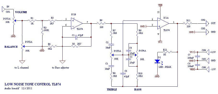
A tone control or pre-amplifier is an amplifier circuit that enhances audio signals. It is important to understand the characteristics, advantages, and disadvantages of various amplifier equipment, as the performance of different amplifiers may not show significant differences. The...
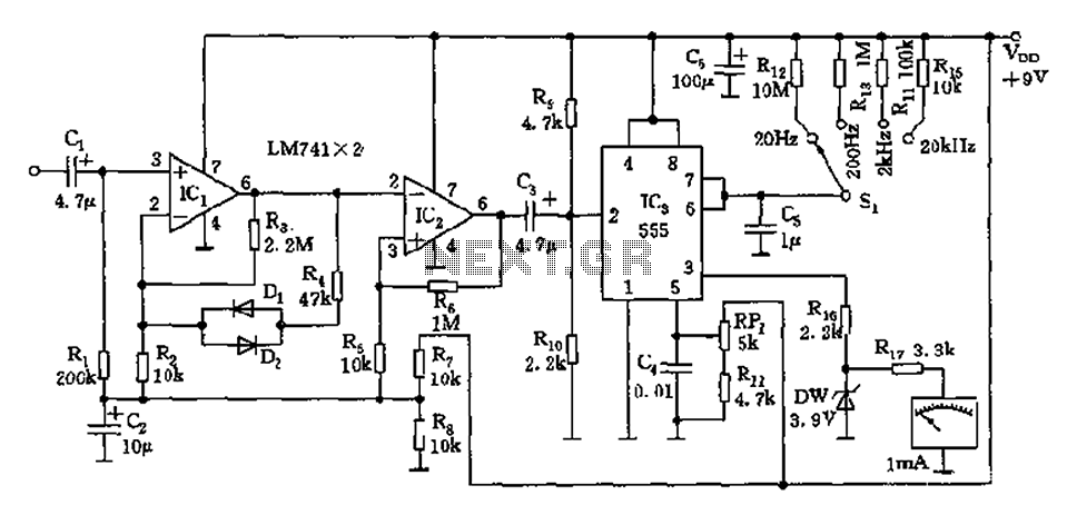
The circuit is a direct-reading frequency meter that utilizes an amplifier and a one-shot trigger circuit, along with table-top components. It is capable of directly detecting a 1mA signal at the read head, with a maximum signal frequency of...
Warning: include(partials/cookie-banner.php): Failed to open stream: Permission denied in /var/www/html/nextgr/view-circuit.php on line 713
Warning: include(): Failed opening 'partials/cookie-banner.php' for inclusion (include_path='.:/usr/share/php') in /var/www/html/nextgr/view-circuit.php on line 713