
High-performance dual-band wireless microphone receiver circuit diagram
The wireless microphone transceiver circuit is designed with several key components and functionalities that enhance its performance and reliability. The circuit is divided into four main sections: the FM head, the intermediate frequency (IF) amplifier, audio processing, and power supply, each playing a crucial role in the overall operation.
The FM head is responsible for capturing the radio frequency signals, which are then filtered through a 10.7MHz IF filter (JT1). This filter is critical for isolating the desired frequency range and ensuring that the signal is clean before it is processed further. The filtered signal is sent to the internal mixer, where it is combined with a local oscillator signal to produce the IF output. This output is then directed to the preamplifier (T1), which amplifies the signal to a suitable level for further processing.
The audio processing section, primarily handled by IC1, includes limiting, amplification, and demodulation stages. The demodulated audio signal is then coupled to the next stage via capacitor C8, which ensures that only the audio content is passed along while blocking any DC components. The audio signal is further processed by IC3, which allows for digital processing and output adjustments. The circuit includes tuning indication and squelch functionality, which helps to manage audio output levels based on the presence of a valid signal.
The power supply section is designed to provide stable voltage levels to the circuit components. The reference voltage source at IC1 ensures consistent performance, while the adjustable resistors R1 and R10 allow fine-tuning of the collector voltages of T1 and T2, ensuring optimal operation. The circuit is powered by 9.6V rechargeable batteries, with an additional 16V external power supply for charging purposes. The inclusion of a voltage regulator (D4) helps to maintain consistent voltage levels during operation.
For successful assembly and debugging of the circuit, it is essential to carefully follow the installation instructions, which involve modifying existing cassette players and ensuring that all components are correctly soldered and tested. After assembly, voltage measurements should be taken at various points in the circuit to verify proper operation. Adjustments to the audio processing gain can be made using potentiometers W1 and W2 to achieve the desired sound quality, allowing for a clear and natural audio output.
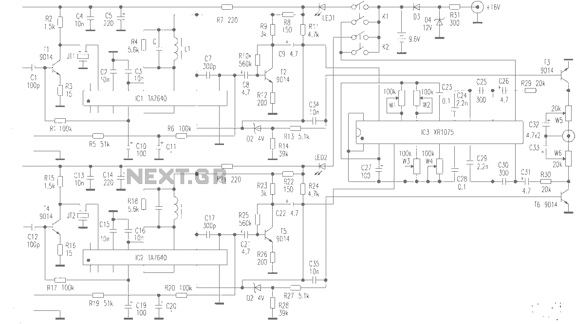
Overall, this wireless microphone transceiver design showcases the potential for repurposing existing technology to create a high-quality audio transmission system, suitable for various applications, including live performances and recordings. With careful attention to component quality and assembly, the resulting device can rival commercially available wireless microphones.Production of high-quality wireless microphone is the desire of many readers, but amateur conditions to produce high-performance receiver is not easy. It opens up ways to use scrap cars FM radio cassette players in part, to increase a XR1075 audio processor, redesigned printing plates, produced a stable and reliable, excellent electrical performance dual-band wireless microphone transceiver system. Emitting part BA1404 dedicated FM transmitter IC. This machine is .png">a circuit diagram of the principle shown below, the production process will now be described below.
The figure shows that the circuit consists of four parts, namely FM head, IF amplifier, audio processing, and power supply. After JT1 10.7MHz IF filter out the basic principles of the signal induced by the antenna from the FM input pin head, the internal high level, after the local oscillator mixer IF output signal of 10.7MHz from foot from C1 to T1 intermediate frequency input preamplifier after signal to IC1 feet, by the internal limiting, amplification, frequency discriminator demodulation audio signal output from the feet, the C8 is coupled to T2 to zoom level to meet the requirements of IC3.
Audio input signal from IC3 feet, after delays in the digital processing portion of the frequency output from the feet. IC1 feet of 2.25V reference voltage source, the tuning indication output pin is used as mute in this circuit.
The principle is: When the feet are the 10.7MHz IF signal is input, this pin is low, T3 off, IC3 pin output audio signal without attenuation; conversely pin is high, the power through R11, D2, R13 to provide bias T3, T3 saturated, so that the audio signal T3, c, e pole into the ground, in order to achieve the purpose of squelch. L1, C composition 10.7MHz frequency selective network, it is also in second place IC1 load, the principle C2, C3 intermediate frequency bypass capacitor, W1, W2, respectively treble and bass audio processor gain adjustment potentiometer, see "newsletter" in the relevant articles.
Installation and commissioning of two bad looking car cassette players (requires FM tuner includes head), removed from the board and tuner and lower welding 10.7MHz filter JT1, IF filter (shape like in the week, usually magnetic cap light blue), TA7640, FM tuner (see photo top right corner of the shape) and other key components for the backup. According to a cabinet sized printing plates, printing plates should be used epoxy boards and large ground, ready to welding components to be mounted on the T3 and T6 after a good overall debugging.
Power (in the way as an example), measuring IC1 pin voltage should be about 6.5V, FM head and feet should be 6V, 0.15V or so feet (M47-type table measurement, digital meter to measure compared to 1.9V), and adjust R1 R10 so that T1, T2 are collector voltage of about 3V. Connected to the amplifier and speakers, at this time if the circuit is normal, the speaker should be larger "rustling" sound, if not rustle, a screwdriver can be used separately touch IC3 feet, T2 base should hum, of taking even IC1 ,, ,, foot, T1 base due louder "giggle" sound, otherwise you should check JT1, L1, IC1 and surrounding components.
Everything is normal rotation FM heads to close a local FM radio station, adjust L1 core to make clear sound. Together with the microphone to adjust the transceiver frequency (avoid the attention of local radio frequency), and finally with a microphone in front of the more familiar music sound better regulate W1, W2 clear, natural sound quality receiver so far, if the microphone to pick up the voice of the main, appropriate to increase the treble (adjust W2).
Another way to adjust the same way. In this case welded T3 and T6, debugging automatic squelch, turn off the transmitter, the corresponding TA7640 feet should be high; should be open to low, or to retune L1. This circuit has not yet adopted the crystal frequency stabilization, but due to the high stability FM head of the wireless microphone transceiver frequency is very stable, has never deviation from the winter solstice, the author of two microphones are used for voice and zither, zither subjective feeling the string is very crisp and beautiful, have a more significant voice sibilance.
As long as elements of quality assurance, the radio microphone with the hundreds of thousands on the finished machine comparable, of course, interested readers can also increase the harmonic generator IC1, IC2 output to improve the clarity of the sound. This machine uses 9.6V rechargeable batteries primary source and the external 16V power supply is designed for battery charging purposes, since R31, limiting the role of regulator D4, so an external power supply for long-term access to the machine.
Related Circuits
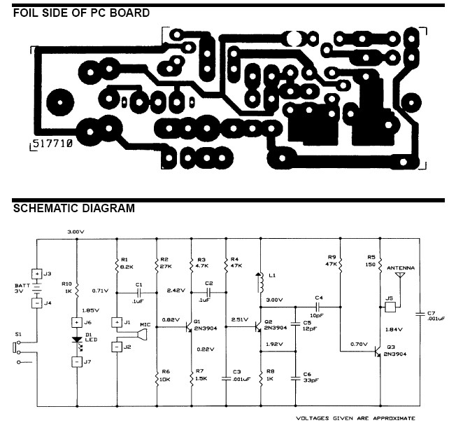
The frequency range for the FM transmission band is 90 MHz (megahertz, or 90 million cycles per second). Due to the variable tuned circuit in the FM transmitter, it can be tuned to a specific frequency within the local...
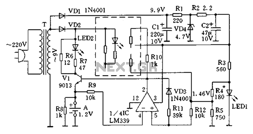
The circuit operates for 10 hours using constant current charging, providing convenience. The electricity from the secondary transformer T is stepped down, with the output directed through VD1 for rectification, followed by R1 and C1 for filtering. VD4 regulates...
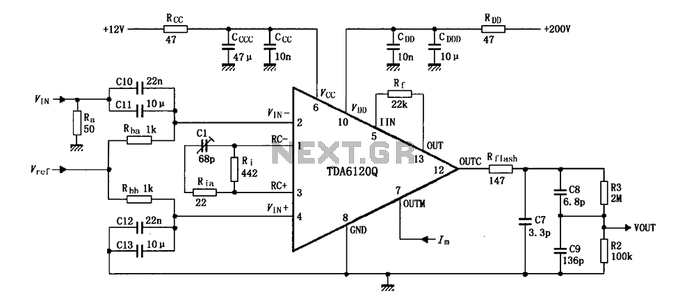
Feedback has indicated that the TDA6120Q test circuit, as shown in the figure, utilizes an input signal (Vi) composed of resistors Ra and capacitors C10 and C11, which are fed into the TDA6120Q at pins 2, 3, and 4....
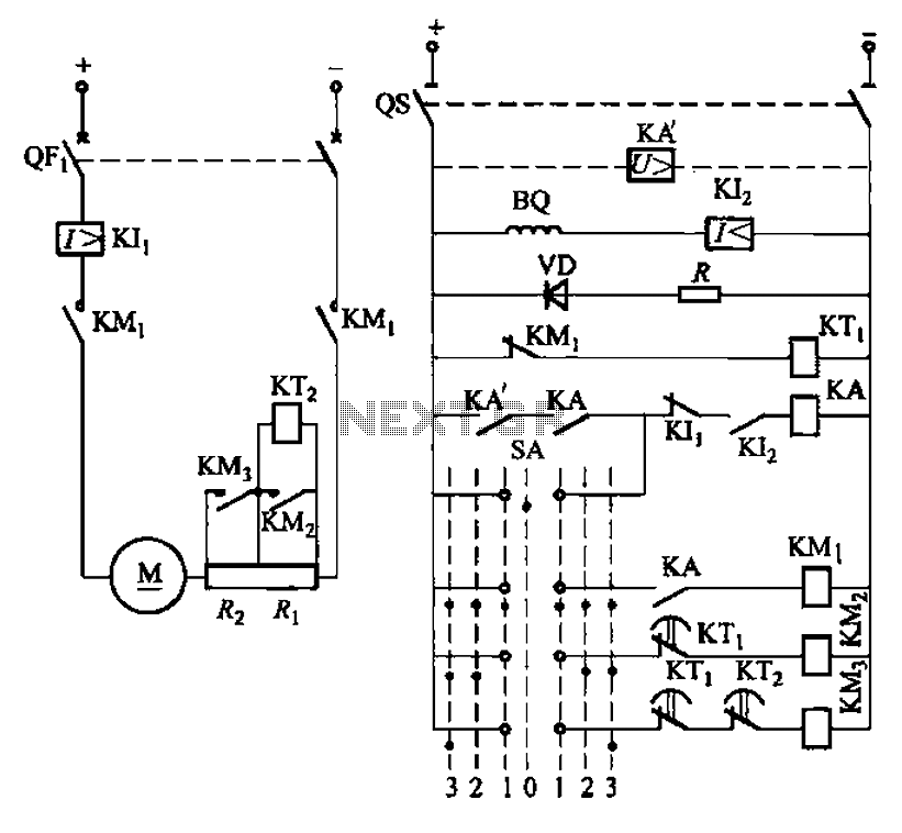
The circuit depicted in Figure 3-190 includes an armature circuit with two startup resistors, Ri and Rz, connected in series through the main switch SA to facilitate starting, stopping, and speed control. During the startup phase, two relays, KTi...
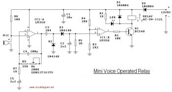
This circuit diagram illustrates a voice-operated relay, which functions similarly to a sound-activated switch circuit. It activates and deactivates the switch based on sound input. The output switch of this circuit is controlled by a relay. The release time...
This schematic illustrates a beeper circuit designed to produce a continuous beep sound while simultaneously flashing an LED. The beeper circuit typically consists of a few key components: a sound-generating device (such as a piezo buzzer), an LED for visual...
Warning: include(partials/cookie-banner.php): Failed to open stream: Permission denied in /var/www/html/nextgr/view-circuit.php on line 713
Warning: include(): Failed opening 'partials/cookie-banner.php' for inclusion (include_path='.:/usr/share/php') in /var/www/html/nextgr/view-circuit.php on line 713