
Boat alarm

The circuit in question is designed as a security mechanism, utilizing resistors R1 and R2 to maintain a stable connection to a power source and ground. In a typical configuration, R1 is connected to a +12 V supply, while R2 is grounded. The removal of either resistor disrupts the circuit's integrity, effectively signaling an unauthorized tampering attempt.
When R1 or R2 is removed, the circuit detects the change in resistance and triggers an alarm system. This alarm is programmed to activate for a duration of about five minutes, serving as a deterrent to potential intruders. The design relies on the principle of voltage division and current flow, where the resistors play a crucial role in maintaining the circuit's normal operation.
In practical applications, this circuit can be integrated into various security systems, including home alarm systems, vehicle anti-theft devices, or any application requiring a hidden security feature. The alarm's five-minute activation period provides sufficient time for the property owner or security personnel to respond to the breach, ensuring a proactive approach to security management.
This schematic can be further enhanced with additional features such as a timer reset mechanism, a notification system that alerts the owner via mobile or SMS, or integration with surveillance cameras for visual confirmation of the alarm trigger. The overall effectiveness of this circuit relies on its simplicity, reliability, and the element of surprise it offers against potential threats.Removing R1 or R2 from the circuit the potential thief breaks a hidden wire that connects R1 to +12 V and R2 to ground) Activates the alarm for about five minutes. 🔗 External reference
Related Circuits
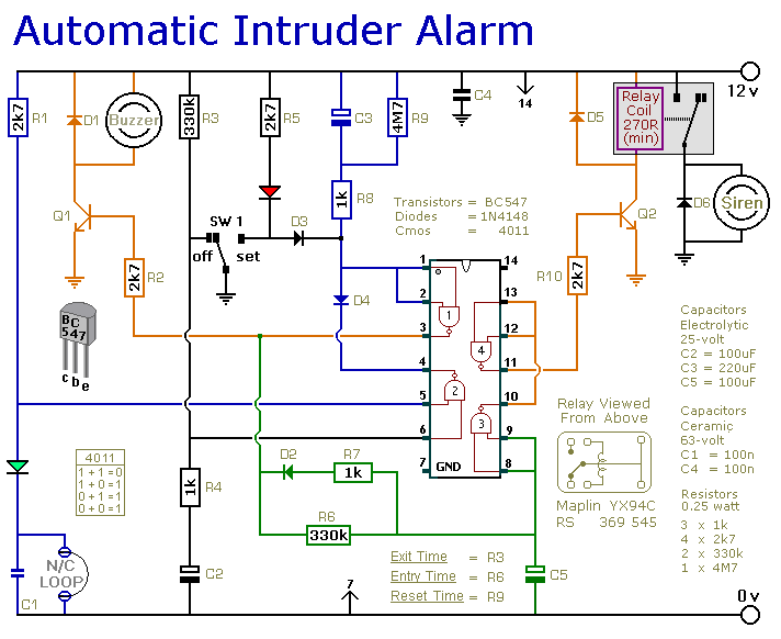
This is a simple single-zone burglar alarm circuit. Its features include automatic Exit and Entry delays and a timed Bell/Siren Cut-Off. It is designed to be used with the usual types of normally-closed input devices such as magnetic reed...

The circuit uses a 555 timer wired as an astable oscillator and powered by the emitter current of the BC109C. Under dry conditions, the transistor will have no bias current and be fully off. As the probes get wet,...
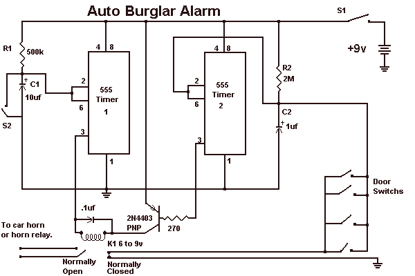
This alarm circuit is based on two 555 timers. The alarm will sound your car horn if anyone opens the car door while the circuit is armed. The timers will allow you to leave the car without sounding the...

This circuit is a wireless car alarm system constructed using two modules: a transmitter module and a receiver module. It operates on FM radio waves and is suitable for vehicles with a power supply of 6-12VDC. A voltage stabilizer...
This circuit, enclosed in a small plastic box, can be placed into a bag or handbag. A small magnet is placed close to the reed switch and connected to the hand or the clothes of the person carrying the...
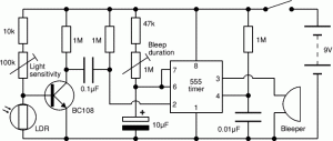
This circuit illustrates the NE555 timer used in a light-sensitive alarm sensor circuit diagram. Features include the ability to detect a sudden shadow falling on the sensor. The NE555 timer is a versatile integrated circuit widely utilized in various timing,...
Warning: include(partials/cookie-banner.php): Failed to open stream: Permission denied in /var/www/html/nextgr/view-circuit.php on line 713
Warning: include(): Failed opening 'partials/cookie-banner.php' for inclusion (include_path='.:/usr/share/php') in /var/www/html/nextgr/view-circuit.php on line 713