
Geiger counter
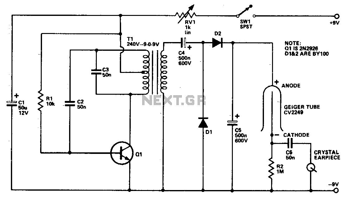
The described circuit features a Geiger tube, which functions as a radiation detector, necessitating a high voltage supply for its operation. The high voltage is generated by a transistor Q1 and its associated components, which serve to amplify the voltage to the level required by the Geiger tube. The transformer is configured in reverse, allowing the secondary winding to act as a Hartley oscillator. This configuration is instrumental in generating the necessary high-frequency oscillations that are vital for the operation of the Geiger tube.
R1 plays a crucial role in providing the base bias for the transistor Q1, ensuring that it operates within the desired region of its characteristic curve. The diodes D1 and D2, along with capacitors C4 and C5, form a voltage doubler circuit. This arrangement effectively doubles the input voltage, enhancing the efficiency of the high voltage supply. The voltage doubler is essential for achieving the high voltage levels required by the Geiger tube without the need for a bulky transformer.
Furthermore, RV1 is a variable resistor that allows for fine-tuning of the output voltage. Proper adjustment of RV1 is critical; it ensures that the clicks generated by the Geiger tube are audible and clear. If the voltage exceeds a specified range, the output may become distorted, resulting in a continuous buzzing noise rather than distinct clicks. This phenomenon can hinder the usability of the Geiger counter, as clear auditory feedback is necessary for effective operation. Therefore, careful calibration of the circuit is imperative to maintain optimal performance and ensure accurate detection of radiation levels.The Geiger tube needs a high voltage supply which consists of Ql and its associated components. The transformer is connected in reverse; the secondary is connected as a Hartley oscillator, and Rl provides base bias. Dl, D2, C4, and C5 comprise a voltage doubler RVl should be set so that each click heard is nice and clean because over a certain voltage range all that will be heard is a continuous buzz. 🔗 External reference
Related Circuits
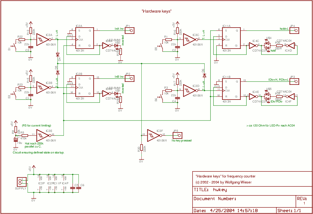
This circuit consists of four nearly identical debounced switches. Each switch features two resistors and one capacitor at the input of its respective Schmitt trigger, which are utilized for debouncing. The output from the Schmitt triggers is directed into...
This circuit illustrates the configuration of an ICM7217 and an ICM7555 designed as a basic frequency counter. The connections between the ICM7217 and a common-cathode LED display are depicted in Figure 12-18. Calibration of the frequency counter is accomplished...
It was designed for an application in a welding machine: there are lots of bits of machinery which are cylindrical in shape and which are subjected to heavy surface wear. For instance ore crushers, and the idler and roller...
The Geiger counter is a scientific instrument that can detect ionizing radiation such as alpha and beta particles and gamma rays. It is capable of detecting a single particle and, although relatively simple, is thus exquisitely sensitive. Radioactivity was...
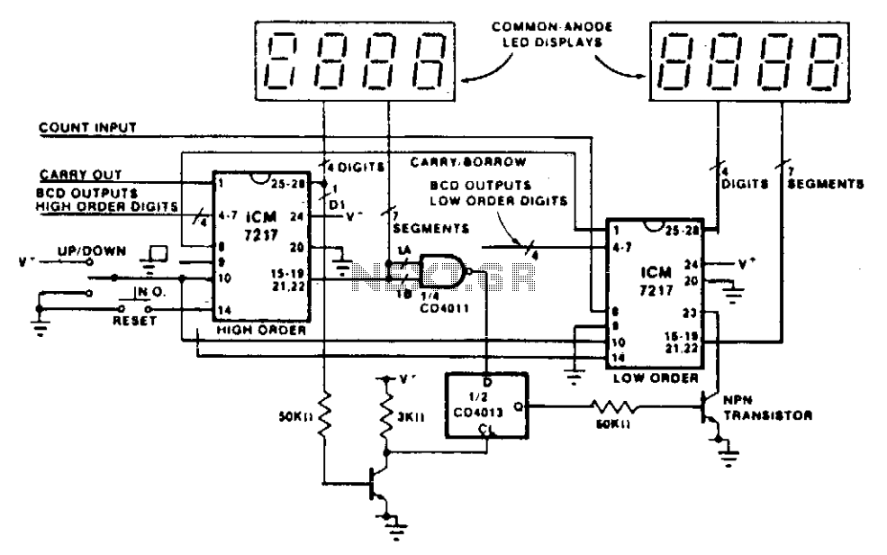
This circuit illustrates the method of cascading counters while maintaining the appropriate leading zero blanking. A NAND gate is employed to determine if a digit is active, as indicated by the activation of either segment a or b on...
This simple counter is useful for frequency measurements of various wireless equipments, especially transmitters, receivers and signal generators in VHF/UHF band. The described frequency counter circuit is designed to accurately measure the frequency of signals in the VHF (Very High...